


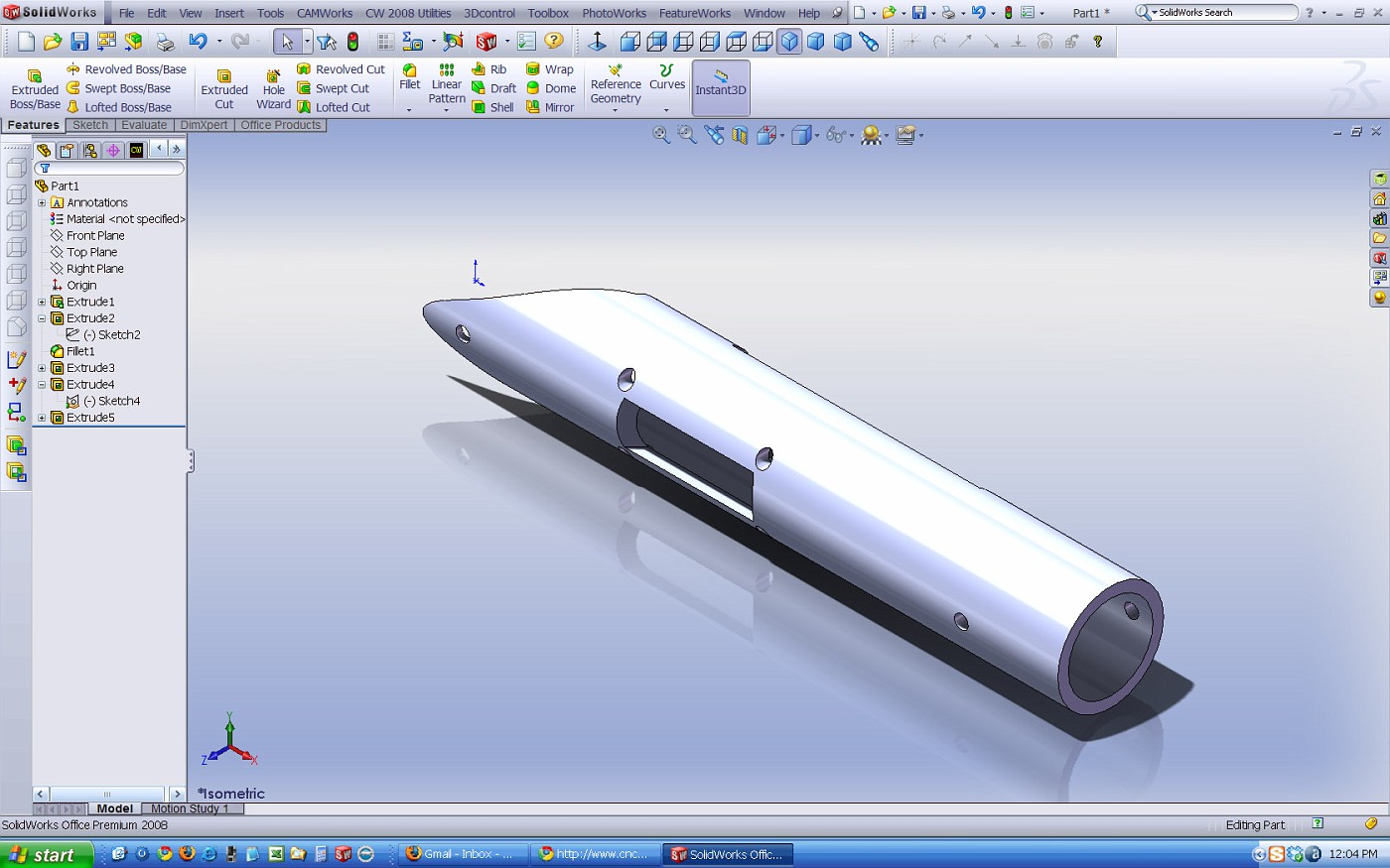
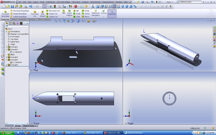
Hello Guys I need some help on cutting a feature out of a solid . I am using solid works 2006 and am new to this software. I bought several training videos to help me start learning but always seem to run into a snag when on my on. What I am trying to do is cut out the section in the drawing (sketch 9 and 14 ,the gray section ) . What is killing me is the radius , I can get a square side through cut no problem. However the cut need to look like the sketch. Any ideas ???
Thanks for any help !!!!

Thread: cut feature
Results 1 to 9 of 9
-
05-23-2009, 12:27 AM #1
 Registered
- Join Date
- Aug 2008
- Posts
- 121
cut feature
-
05-23-2009, 01:11 AM #2
Banned
- Join Date
- Apr 2004
- Posts
- 63
I'm an Inventor guy myself, but you should be able to use the same in Solidworks. If I'm seeing what you want correctly, I would create an X Y plane, or use the one that may already be there depending on how you created the tube, that goes thru the center of the part (parallel to your plane 1, but in the center of the tube). then draw the half circle side profile of your cutout and extrude/cut in both directions the required amount.
-
05-23-2009, 02:15 AM #3
Gold Member
- Join Date
- Feb 2009
- Posts
- 2143
That will work. Originally Posted by Rube

You don't need the plane to be on the right plane, of course (in SW, I don't know Inventor). You can draw the cutout on the top layer (or any plane parallel to the top layer, which you can created with "Reference Geometry"), then use the Extrude Cut command to cut the slot. You will start the cut from an offset of the sketch plane, and for a Blind distance the thickness of the cut.
It looks like the OP is trying to "draw" the 3D cutout itself - this is the WRONG approach! You draw a 2D view of the cut, and extrude it in the third dimension.
-
05-23-2009, 03:47 AM #4
Registered
- Join Date
- Jan 2009
- Posts
- 56

You are right, too much sketch.
Use the arc segment as a sweep path and on the 3rd plane sketch a rectangle to use as a cutting tool.
Or, create or use a plane thru the center of the long axis, sketch and extrude cut midplane.
TM
-
05-23-2009, 01:33 PM #5
Banned
- Join Date
- Apr 2004
- Posts
- 63
That could be a pretty handy feature. I could go from and to reference faces that exist on the model if the sketch is on another plane, but not an offset from the sketch plane. It would be more work to make sure the relationship is maintained though, if the diameter of the tube changes. The midplane solution is an easier better one in this case. Besides, that plane more than likely already exist, and is how I would have done virtually all the features I see on that part. He was probably just trying different things, which is good, as obviously there are many ways to do it. I assume he drew that sketch to show his intent, and don't believe he was trying to extrude that. Originally Posted by mcphill
-
05-23-2009, 04:52 PM #6
Gold Member
- Join Date
- Feb 2009
- Posts
- 2143
No offense to the OP, but I think you are assuming too much about his intent. 3D packages are VERY different from 2D, and until he has his "AHA" moment, it will be tough. Hopefully some of the posts in this thread will help him out. If the OP is still around, please repost to this thread so we can hear how you are coming along! Originally Posted by Rube
Is this what you want? If you have any questions on how it was done, I would be glad to help.
-
05-25-2009, 09:53 PM #7
Registered
- Join Date
- Aug 2008
- Posts
- 121
Thanks
Hello all and thanks for the help . I got my problem solved with a simple 2d drawing and a extrude cut in both directions.
Now how is the best way to put some threads ( 1.0625 x 16 TPI ) in the end of this action ???
Thanks again for all the help !!!!
-
05-27-2009, 09:37 PM #8
Gold Member
- Join Date
- Feb 2009
- Posts
- 2143
SolidWorks won't model the actual threads easily. You can use the Hole Wizard to specify the location, size, and depth of the threads, and the callouts will populate in to 2D drawings created from the model using this data. However, visually all you really get are some "cartoon" graphics of the threads - they are not correct, even with "cosmetic threads" turned on.
If you want it to look right aesthetically (doesn't help to get it machined!, just for looks in the model), you need to model up the threads. This is best done be creating a helix with the right pitch and the thread OD or ID, and then sweep (extrude or cut, depending on the helix you chose) a thread-pitch cross section along the helix. Again, this is WAY overkill if you just want the part made/quoted, but is needed if you want it to look like the real part for "marketing purposes".
Originally Posted by hall6ppc
-
05-28-2009, 03:00 AM #9
Registered
- Join Date
- Jan 2009
- Posts
- 56
I agree, although I'm guilty of creating real threads just to see how they interact within an assembly.
In this case, the id would be the minor diameter of the thread and I would use INSERT | ANNOTATIONS | COSMETIC THREADS and add the thread information there. This way it shows in the detail drawing when you use hole callout.
TM

 Reply With Quote
Similar Threads
-
feature cam to dxf
By daleman in forum FeatureCAM CAD/CAMReplies: 4Last Post: 07-15-2011, 02:59 PM -
Request DNC feature
By single phase in forum NCPlot G-Code editor / backplotterReplies: 3Last Post: 12-14-2007, 04:04 AM -
Feature Cam Post For 04 Tl-1
By DATTAMAN in forum Haas MillsReplies: 0Last Post: 02-04-2005, 04:27 PM
