


Let me start by saying I'm a hobby machinist.
I recently bought a little book, "Gears and Gear Cutting". Toward the end it talks about making one's own gear cutters, and points out the need for a multi-tooth cutter to be relieved and further includes plans for a tool that will do that relieving operation on a lathe. The tool oscillates and ratchets the gear cutter blank so that one tooth is worked on with each revolution. The parts of the tool seem well within the ability of the home machinist, there are about a dozen parts. The invention was in a Victorian tool catalog and called the Eureka.
The book also points out that a perfect profile of a gear tooth cannot be easily be cut with home type machinery, but that the profile can be very closely approximated by the arc of a circle and therefore a forming tool using two circular cutters can be used to create a gear cutter.
So it occurs to me that with a home CNC lathe and the Eureka, one could make rather exact gear cutters.
I'm interested in hearing any and all comments from those who might add some insight.
Ozzie
Thread: Making Gear cutters
Results 1 to 20 of 21
-
06-24-2009, 01:53 PM #1
 Registered
- Join Date
- Jul 2004
- Posts
- 442
Making Gear cutters
-
06-24-2009, 03:15 PM #2
Registered
- Join Date
- Mar 2008
- Posts
- 256
This sounds basically like how a piston lathe makes non-cylindrical pistons, by plunging/withdrawing the cutter twice per revolution. Is this type of action basically what you are talking about?
If so, I think this will require a great deal more aggressive plunging than what is seen on a piston lathe, and will therefore require a highly relieved turning bit to do the cutting, which will weaken it. Weak cutter + interrupted cut = no bueno, so that's one challenge to overcome.
What are you referring to by ratchetting the blank?
Also, how is the oscillation of the tool to be synchronized with the rotation of the spindle? Is that what the ratchetting is about?
-
06-24-2009, 04:04 PM #3
Registered
- Join Date
- Mar 2006
- Posts
- 2712
Ozzie, you might consider having the form relief "back-off" done on a wire EDM.
Gear hobs and other gear cutting tools are very "fussy" in thier design and manufacture.
Dick ZDZASTR
-
06-24-2009, 04:07 PM #4
Registered
- Join Date
- Jul 2004
- Posts
- 442
After posting I did some further searching and found that the subject has been discussed, fairly extensively, in this forum.
CNCzone.com-The Ultimate Machinist Community > MetalWorking > General Machining Discussion > gear hobbing....
Some of the Eureka design info looks quite different from the plans I have, though the principal is the same. The plans I have I think were reverse engineered by Dr. Chaddock of Quorn fame.
There's not much discussion of combining CNC with the relieving device.
I think that a G-code designed to cut the cutter form, could do that first and then be used with the device to do the relieving. The lathe cutting tool could be just a square carbide tool, (a cutoff tool), one corner for each side of the profile. Given an accurate profile drawing, a good CAM program would make a very respectable G-code.
Ozzie
-
06-24-2009, 04:19 PM #5
Registered
- Join Date
- Jul 2004
- Posts
- 442
Thanks Dick, Originally Posted by RICHARD ZASTROW

Though I have a rough idea of what an EDM is and does, it's not clear to me how that is better.
But in any case, as I said I'm only a hobby guy. I don't have an EDM and I hope you don't convince me that I need one because there is only room for a small package of toothpicks left in the garage.
Ozzie
-
06-24-2009, 11:09 PM #6
Registered
- Join Date
- Mar 2006
- Posts
- 2712
Ozzie, actually I meant to "farm out" that operation to ????. After further consideration, I don't think that would accomplish the total form relief back-off. I know the hob manufacturers use EDM in their processing, but I don't know that process.
The hobs are very expensive and their use complicated. You may be better off using individual gear form milling cutters. These are reasonably priced and readily available.
Dick ZDZASTR
-
06-25-2009, 11:50 PM #7
Registered
- Join Date
- Mar 2005
- Posts
- 1136
you know you need a universal mill or hobbing machine to use the hobs right? having said that there's been lots of home shop hob relief setups made including Eureka, there’s one nice example here or the home shop bbs site. you'll also have to set up a the leadscrew to cut diametrical pitches. Find and search indexes of Model engineer magazine and model engineer workshop for several home shop builds of hob relievers and hobbing machines
There's nothing about it that isn’t doable, its just that who makes enough gears to make it worthwhile to make all the tooling AND a hobber (if you don’t have a universal mill). if you do do it, one cutter will make all your gears of a give size and you'll be able to do spur and helical gears
If its a small number of light duty gears, there's a cheat using what i call a faceted hob. its really just a profile cutter - Peter Harrison has a great how to on his site.....but keep in mind this is NOT a hob and the tooth form will be a faceted approximation of an involute profile
http://www.helicron.net/workshop/gearcutting/
Theoretically, the whole hob including relieving should be able to be cut on a cnc lathe.
-
06-26-2009, 02:36 AM #8
Member
- Join Date
- Aug 2005
- Posts
- 1622
This is a fantastic learning experience, if it is a non-standard gear. But....several hours to create one gear cutter and a gear blank and then cut teeth will shortly become drudgery. Been there a few times making cheap tool steel gear cutters manually, so I really appreciate the shortest options possible.
If the gear DP and tooth count is known, it may be cheaper to just buy pinion stock or gear blanks from places like Stock Drive Products, Browning or Martin, than making hobs or buy individual involute gear cutters for less than 10/year. Pinion Wire or Pinion Stock is just parted off in the lathe with or without a hub. Add a set screw or keyway in a secondary operation.
This is of course if there is a choice or the time spent ends up as a worthwhile result.
Tons of youtube video's show gear cutting and hobs for both home and commercial operations.
Here is one showing the Eurika in action. It appears you also need to create chasers for to advance the cutter.
[ame="http://www.youtube.com/watch?v=kJ8kyC_bpHs"]YouTube - Charles Lessig's Hob Reliever Eureka Balzer Gear Cutting[/ame]
DC
-
06-26-2009, 04:50 AM #9
Moderator
- Join Date
- Mar 2003
- Posts
- 4826
Many years ago, I had the gear cutter bug myself, and came up with a hydraulic relieving attachment for use on a larger, heavier lathe ( a 19" Summit). The setup consisted of an 8 lobed cam wheel, about 8" diameter, which was affixed to a 1" mandrel. The cutter blank was mounted on the other end of this mandrel.
Then the whole thing was set up in the lathe chuck, using the tailstock to support the outer end. On the lathe bed, I had a short stroke hydraulic cylinder beneath the 8 lobed camwheel. From that cylinder I ran a hose to a small slave cylinder that I had built to mount in the toolpost. The slave cylinder simply had a square hole Sturdy sleeve inserted into the end of its shaft, out of which, the toolbit projected.
Now running the lathe at low speed, the 8 lobed cam wheel thumped along over top of the master cylinder beneath, producing 8 strokes per rev. The spring loaded slave cylinder in the toolpost pulsed out in unison with the impulse from the master, and the spring inside the slave forced the master to stay in contact with the cam wheel.
So then the trick was shaping the toothform on the cutter blank, using a template. The profile was truly form relieved. I always worked with a round cutter disk blank, and then cut the tooth faces afterwards, because I could then mill away the most imperfect part of the soft cutter where the tool was doing the retracting.
I would think this could be done very very nicely on a cnc lathe, but I've never seen one with a cycle that would properly automate the slide motion in step with spindle rotation.First you get good, then you get fast. Then grouchiness sets in.
(Note: The opinions expressed in this post are my own and are not necessarily those of CNCzone and its management)
-
06-26-2009, 10:29 AM #10
Registered
- Join Date
- Apr 2007
- Posts
- 151
Single Point Cutter
Ossie
Unless you need your gears to perform at high speed, it is possable to make a simple cutter, the shape depends on the No of teeth on gear. Take a square lathe tool and hold it in a tool clamp using the worn edge of your grinding wheel you can shape the flanks, make sure it is slightly angled for relive, use a magnifier to observe equal sides. You will need to make a holder to suit your mill, essentally a square fly cutter, using a dividing head and the cutter on centre line cut the gear in the normal way.
You might need to experiment with shapes, but its supprising simple process, give it a try
Good Luck
Mike
-
07-03-2009, 05:41 AM #11
Registered
- Join Date
- Sep 2006
- Posts
- 36
Single tooth involute cutters.
There is also this type, with a cnc lathe you can get the form dead on. It's mounted eccentric to provide the clearance while cutting.
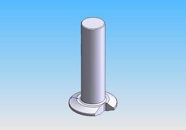
Regrind face radially to center, to maintain form. Slow but for home use?
Cheers,
-
07-03-2009, 06:27 PM #12
Registered
- Join Date
- Mar 2006
- Posts
- 2712
For use in a home shop, I believe Les has the best solution so far.
Dick ZDZASTR
-
07-18-2009, 03:44 PM #13
Registered
- Join Date
- Jul 2004
- Posts
- 442
Re-visit, 2 ideas
I've been thinking about this whole subject and I'd like some thoughts on two ideas.
If one cuts gears with a cutter having teeth shaped like a rack you get an acceptable gear, except that the profile is faceted. You only need one cutter for all diameters of gears, (number of teeth). If, after making the whole gear that way, one were to lower the cutter (Z axis), half a tooth, and change the rotational position of the part, (gear), in the indexing head, by half a tooth, it seems to me that the number of facets would increase, making a smoother profile. With CNC a vertical move of the Z axis could be synchronized with rotation in a rotary head and all facets would be smoothed making a perfect tooth. ?????
Idea 2.
In hobbing, one of the difficulties is that one needs a gear train to match the relative rotation of the hobb and the work piece at an exact ratio. But this is the CNCZone. Couldn't one just drive two spindles/rotary-heads at the proper ratio, eliminating all that gearing. In a lathe, a Hobb could be set up in a chuck or between centers. The gear blank would be mounted on a rotary head set to the proper angles. Then using a threading routine in the controller, it could be made to drive the rotary head rather than the Z axis.
I'd like to hear comments on each idea. Anyone tried either?
Ozzie
-
07-18-2009, 05:07 PM #14
Registered
- Join Date
- Mar 2008
- Posts
- 256
Since it's a CNC and we can quickly and easily position the cutter and 4th axis anywhere we want, we don't even need a rack shaped cutter. An endmill will do. You just have to take 2 shots at each tooth, one for each face. Yes, you can increase the accuracy of the profile by calculating more tangent points on the tooth face, and taking more cuts. I'm not sure that the method you proposed is the best way of calculating those tangent points, but I think you're on the right track. I'm working on a macro to do this right now. I'm having some success. Originally Posted by ozzie34231
EDIT: Re-read your post, missed the first time that you were talking about a dividing head/manual 4th axis. It would require god-like patience and focus to take all the cuts necessary to get even a moderately smooth tooth face with this method. CNC is the only reasonable way.
Also, synchronizing the rotation of 4th axis with cutter (in the CNC scenario) would not result in the perfectly smooth profile you seek, it would simply make the facets ramp up the tooth face, instead of running straight across it. Lots and lots of facets is the way to get a smooth tooth. /EDIT
EDIT2: BTW, your second idea is spot on, theoretically. I'm sure there are others better qualified to speak to the practicality of it, but I like the idea. /EDIT2
-
07-18-2009, 07:51 PM #15
Registered
- Join Date
- Jul 2004
- Posts
- 442
[QUOTE=flick;640229]Since it's a CNC and we can quickly and easily position the cutter and 4th axis anywhere we want, we don't even need a rack shaped cutter. An endmill will do.
Thanks Flick,
Yes, but you would need a shaped endmill; or using a flat or ball end one would need a super high number of passes to get a smooth profile.
Using a rack shaped cutter with about 6-10 teeth, CNC could move the cutter and gear blank synchronously, as if a gear were moving along a rack. I think that produces a perfect tooth on the gear. And again one cutter will do for all gears of that angle and pitch, from an infinite number to some very low number of teeth, 8?
As for idea 2;
The more I think about it the less sure I am, at least about using a threading cycle. In normal threading there is a place for sync. to start where there is no thread. In this case we have no such place; the gear is continuous. I'm reasonably sure it can be accomplished but maybe not with the standard canned threading cycle like I have in Mach 3, (G76). But maybe with some form of G33 custom written code.
I'm thinking that synchronization must start and then the X axis of the lathe must move in to contact and then make progressively deeper cuts, and still while in sync. the x must retract.
Ozzie
-
07-18-2009, 08:44 PM #16
Registered
- Join Date
- Mar 2006
- Posts
- 2712
There were threads some time back where a tap was driven by the lathe spindle. There was a fixture attached to the cross slide. The fixture rotated on a bearing while holding holding the blank. This produced a worm wheel from the blank by threading the worm wheel with the tap.
Dick ZDZASTR
-
07-18-2009, 08:54 PM #17
Registered
- Join Date
- Jul 2004
- Posts
- 442
Yes Dick,
that method has also been used to make a gear using a regular Hobb. Pre-cut slots in the gear blank enable the Hobb to drive the future gear. From what I've read the success is widely varied and depends on things like the feed rate into the Hobb, the turning resistance on the gear blank, sharpness of the Hobb, etc. I guess it all depends on your expectations versus the effort you're willing to put in. That method certainly is less reliable than driving the gear blank.
Ozzie
-
07-18-2009, 10:58 PM #18
Registered
- Join Date
- Mar 2008
- Posts
- 256
By a shaped endmill I presume you mean a tapered one - tapered at the pressure angle of the gear to be produced, much like the teeth on a hob. A normal flat endmill would not require more passes to generate the same quality of profile as one tapered in the above manner. You merely have to position it so that you are cutting with side of it tangent to the curve of the flank, which is all a tapered one would be doing anyway. It takes a little trig to figure out the difference in Y and Z position of the endmill, and angular position of the blank, but that's what computers are for. Originally Posted by ozzie34231
If you're not convinced, picture the setup in your head - looking down the x axis from the end of your milling table at a tapered endmill cutting a gear blank with a 20 deg. pressure angle. Now rotate your point of view by 20 degrees. Voila, it's the same thing as cutting with the side of a normal flat endmill, just at a different angular and co-ordinate location.
There is no difference between moving the rack shaped cutter in synchronization with the gear blank and doing the same with a tapered end mill, or with a flat endmill. As I said before, this would merely cause your facets to climb/roll/creep up the face of the tooth as the point of tangency changed during the course of the cut. Originally Posted by ozzie34231
Also, I don't think there is a difference between that and the natural generating action of a hob, since during the 360 degrees of a hobs rotation, one cutting edge on that hob only actually cuts a single point tangent to the involute curve of the tooth, at the point where it is perpendicular to the axis of the blank, and the height of the scallops it leaves is the same as any other tool with a straight edged cutting profile - flat endmill, tapered endmill, or rack shaped cutter.
If there is an advantage to hobbing, it comes from the high edge density, combined with the fact that it works on several teeth at once. I do recall at one shop where I worked that it took all day to produce a few feet of splined shafting, about 6" diameter. I don't know the exact details, because I was just the sawshack/forklift/broom & shovel kid back then, and I didn't ask as many questions as I should have.
A flat endmill can do any pressure angle, any number of teeth, and any pitch for which it can fit in the root. It is actually a more versatile tool, as long as you can program the path. Originally Posted by ozzie34231
The advantage of the rack shaped cutter is that it can work on more than one tooth at once, but I'm not so sure it would actually be more productive than an endmill. It will have a larger diameter, which means a slower spindle speed, and using the design illustrated above by Les to achieve profile relief it is limited to 1 tooth, and both those factors translate into slower feeds at the same chipload/tooth.
-
07-19-2009, 05:21 AM #19
Registered
- Join Date
- Mar 2005
- Posts
- 1136
depends what acceptable is defined as. its a long way from a perfect tooth, it works and isn't too bad for slow non demand situations, but the action is not smooth, at speed it'll be noisy and wear wrecking the clearance quickly I 'd think Originally Posted by ozzie34231
your lathe set up requires a linear motion at an angle to the lathe's axis, how does the blank, mounted in the rotary head move in and out? Otherwise you're just going to cut a worm gearIdea 2.
In hobbing, one of the difficulties is that one needs a gear train to match the relative rotation of the hobb and the work piece at an exact ratio. But this is the CNCZone. Couldn't one just drive two spindles/rotary-heads at the proper ratio, eliminating all that gearing. In a lathe, a Hobb could be set up in a chuck or between centers. The gear blank would be mounted on a rotary head set to the proper angles. Then using a threading routine in the controller, it could be made to drive the rotary head rather than the Z axis.
John Stevenson has done this, electronically coupling blank axis and the hobs, and posted a number of pics and a description on the home shop bbs. works well, and lets you do proper helical gears as well
of course you need a universal mill so the table can be turned to the helix angle of the hob....then again they don't go for much money and it would be a nice addition....
I can't see an endmill working as well as a hob, just based on the finish differences and what a pita it as to use the side of an end mill in a vertical mill vs a larger cutter in a horizontal. unless the DP was massive, the end mill would to be small which exacerbates the issue.
-
12-07-2013, 11:27 AM #20
Registered
- Join Date
- Dec 2013
- Posts
- 1
I also glad to learn about gear cutters. actually i am student from that similar field and this about thread non-standard gear and i want to learn about standard gear gear. can admin help me out that what is the main quality of standard gear.

 Reply With Quote
Similar Threads
-
gear making tool or wizard of some sort
By Craigpat in forum SolidworksReplies: 3Last Post: 08-24-2013, 03:21 PM -
Making a four stage spur gear box? (how to )
By youthreewire in forum Mechanical Calculations/Engineering DesignReplies: 14Last Post: 02-27-2009, 04:11 AM -
where to buy gear cutters and splinde broaches
By Hiredgun in forum I.C. EnginesReplies: 7Last Post: 03-20-2008, 01:35 AM -
What tools to use for Gear making?
By mooreaa in forum MetalWork DiscussionReplies: 3Last Post: 02-04-2008, 03:25 AM -
New member looking for fine gear cutters.
By Laszlo in forum Community Club HouseReplies: 2Last Post: 06-16-2004, 01:58 AM
