


I few months ago I picked up a Hercus Compulathe from a friend. Heres what has gone on since I got it. Mostly reposting from another site where I was keeping an ongoing log on it.
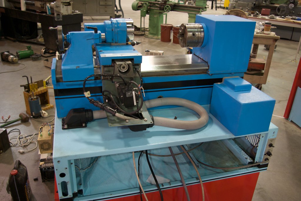
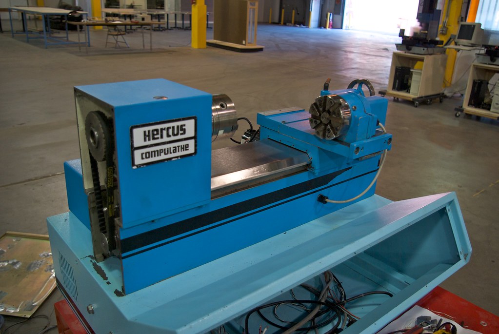
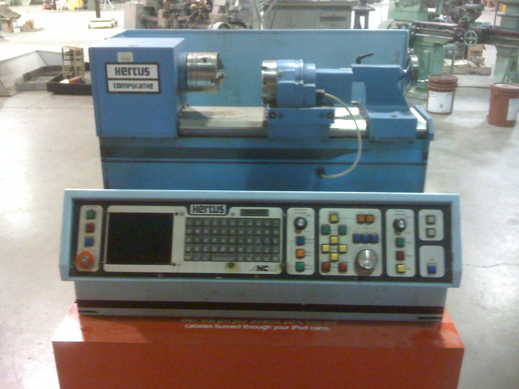
Bought a little CNC lathe today. Neat little Hercus Compulathe. 8" swing ~14" between centers. 8 tool turret. Made in '86.
Really well built. Two people can barely lift it. It is a V way machine but there is a integral stainless chip guard that keep the chips out of where they should not. The carriage and tailstock actually wrap around and under the guard. The 3 jaw chuck is made by Pratt-Bernard.
Its all servo driven Resolvers on the axis' as well as the spindle.
Bad thing is the control wont boot up. Just a solid cursor. Now if I can just find a SVGA LCD screen to replace the monitor I can retrofit it. I have a couple 200 watt brushless servos and drives with step/dir inputs made by SimpleServo. Might be a good option for the machine.
Thread: Hercus Compulathe retrofit
Results 1 to 20 of 20
-
07-11-2009, 09:24 AM #1
 Registered
- Join Date
- Apr 2006
- Posts
- 158
Hercus Compulathe retrofit
-
07-11-2009, 09:26 AM #2
Registered
- Join Date
- Apr 2006
- Posts
- 158
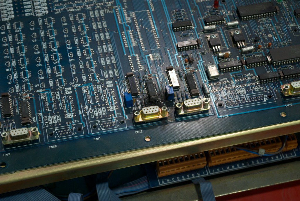
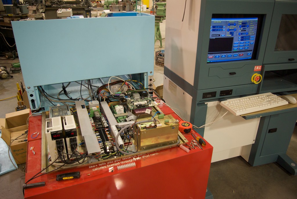
Got the manuals, but... Found the problem. Nice burn spot on the main board. Around one of the analog connections to the servo drive for one of the axis's are some burned up components. Only thing i can think of is something happened in the servo drive and high current got into the main board. The board was even burned on the back side!
So I have three routes to repair it. The control is toast and even if I did repair I would still have a 23 year old control. First, I can keep the original servos and drive them with something like the Gecko 320 servo drives and and install encoders on them for feedback. This would be the most expensive route. Somewhat time consuming as I need to pull the bed off to run new encoder wires. Also the resolver in the head would have to be replaced.
Second, I found Analog Devices makes an IC that drives a resolver and outputs position info in serial, parallel, and quadrature with an index pulse at 1024 counts per rev. Accuracy is 11 arc minutes. Plenty good for this. The IC's are around $18 for two. The circuit is real simple to just get the ABZ signals out of it. It is a 44 pin LQFP so I will have to have a board made to do the two axis plus the spindle. Again I would use geckos or an equivalent brush type servo drives.
Last is I have two 200 watt SimpleServo Ac Brushless Servo motors with brakes and drives. About the same physical size as the original motors. The drives have Step/Dir inputs so I can hook up to any generic parallel port with little issue. Since I have the motors and drives this would be the cheapest but most time consuming as I need to modify brackets and bore the drive pulleys. Also have to pull the bed to run the new wires.
Tough decision. Leaning towards the second option. I think I can use the original front panel. The opening is 7" for the display so I might be able to find a small LCD to go in its place. Most of the buttons and MPG can be reused I think. May end up going with something like the homann designs ModIO board:
http://homanndesigns.com/store/index...roducts_ id=4
Here are a couple better pics:
-
07-11-2009, 09:28 AM #3
Registered
- Join Date
- Apr 2006
- Posts
- 158
4/26/09
Oh, I paid $1200 for it. The iron alone is worth it. Pulled it apart today. The ways are in perfect condition. Two V ways and they are hardened and ground. I cant get over how well its built. Even the chip covers are cast. Very well machined. The saddle glides along the ways with ease.
The two ICs are a digital to analog converter and quad op-amp. Also some burned up decoupling caps and ICs. Bus voltage was good so the board should have done something. Its toast. The output here was a positive or negative voltage signal that drove the servo amp. Dont know if it was +/-10v or not but I bet it was. The servo drive board can be seen in the bottom right corner of this pic:
http://farm4.static.flickr.com/3615/...7f25b87e_b.jpg
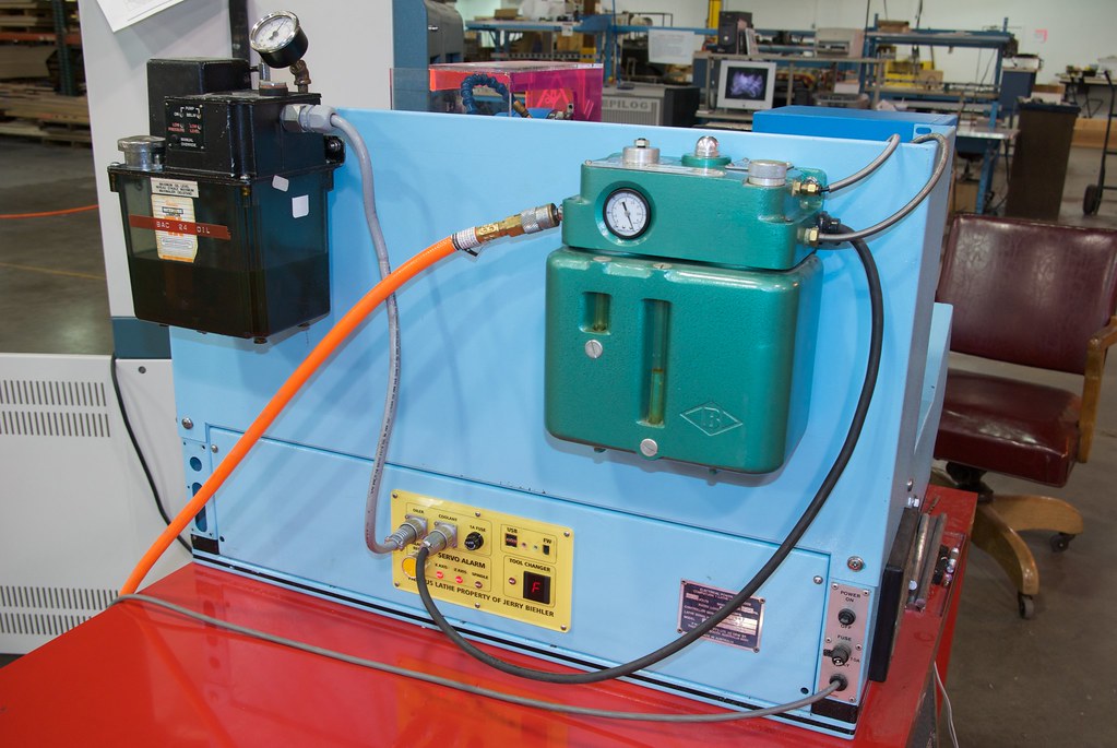
The transformer drives all of the power electronics like the spindle control which is in the bottom left corner. There is a switching supply beneath the main board that supplies +/- 15v, 24v, and 5v.
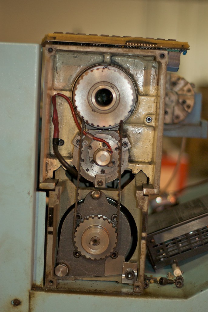
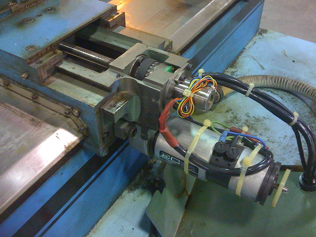
Like I mentioned above I started gutting it today. Pulled the servos and resolvers. Found the limits. The screws are not ball screws. They are something called a satellite roller screw made by Rollvis in Switzerland http://www.rollvis.com/EN/index.htm. The Z axis does not feel so hot so I might go ahead and replace it with a ball screw. Tried cleaning but it dosnt look good. The X screw seems OK.
The brushless servos I have will fit in the spots where the old motors are. I can direct drive the X screw. Max speed of 472 inches per min that way.
The last goofy thing I have found is the spindle .55kw DC spindle motor is rated for 180v, yet the original stock drive runs off of 120v. Might just go ahead and replace the motor too.
-
07-11-2009, 09:31 AM #4
Registered
- Join Date
- Apr 2006
- Posts
- 158
4/28/09
In the past couple days I have taken the machine pretty much apart. There is space on existing Z motor mount so I chucked that up on the 4 jaw on the big series 60 at work and bored it to fit the mount the servo has (50MM boss). They are not NEMA but similar size. Still need to drill and tap the holes.
The Y axis is going to be a little more interesting. I had planned on direct driving the screw but the cast aluminum cover that protects it is in the way. So I need to belt drive it. Still trying to figure out the best way. The shaft on the servos are 14mm so I am going to have to use a larger pulley than stock. I may have to make a shaft extension and a nose similar to the old motor to mount it in the place of the old motor.
Next is the spindle motor. The motor is rated .55kw at 180v. This is a normal voltage for 240v SCR drives. But they were running the thing at 90v. Makes no sense as the spindle drive was definitely designed to run on 120v. It is ran of the 115v secondary of the big power transformer. My first stab at it was to use a 750 watt brushless servo. I have an aerotech drive that should have run it but it wont since the motor was designed to run off of a 240volt drive. The aerotech drive I have runs off 120v and wont put out enough to bring the motor to full speed. So the next best thing I can think of is getting a new 240v PM motor drive and use a auto transformer to get the voltage I need to run it. Or find a 240v input servo drive that will run the motor.
I dug through my garage and found a kollmorgen goldline nema 34 frame motor that may work. I have a couple drives that will work with its resolver feedback. I will just have to build a voltage doubler to get the bus voltage it needs off of 120v.
4/29/09
They made this and a cnc mill called the compumill (Creative naming, huh?) I think I saw something online mentioning a Compulathe 2. I think they were intended for the educational market. There was a version of the machine I have that was made with coolant. I have a spare Bijur spraymist that ought to do the trick. Yes, Hercus in Australia.
There are 4 zerks on the machine, two on the ways and two on the cross slide. The two on the ways feed 4 little holes on each way. With the tailstock at the end of the bed and the carriage at home the holes are right under the sliding surfaces. I do have a small timed pressure way lube pump that would work good to oil things.
I'm not painting it! I can tell you that. If everything goes as I hope you wont be able to tell the difference before and after. Well, maybe a little cleaner!
If there is anything I am going to go through and redo like I did the monarch it will be the old SB9A. It needs it...
4/30/09
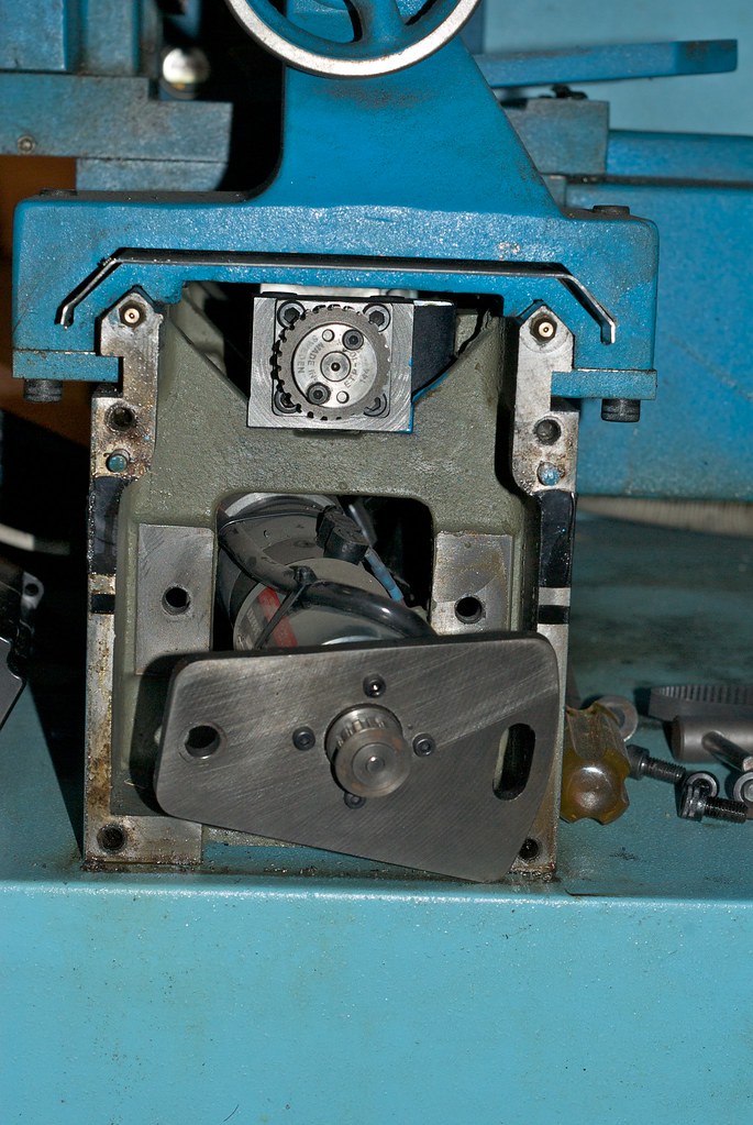
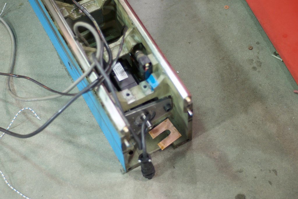
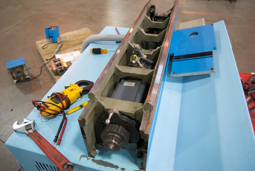
Today I installed the Z axis motor. Fits good. Enough movement to allow belt tensioning. Heres pics of the lathe without the chip guard and lead screw. Sorry about the pic. Had my aperture a bit too open.
Here are the motors I am using for X and Z. SimpleServo motors made by ACTech/Lenze. 200 watts (~1/4HP) with brake, 3000 RPM rated, 4500 Max, 2000 line encoders. The drives run off 120v and take step/dir inputs as well as analog. Drives are tuned through a pc with a serial port.
http://farm4.static.flickr.com/3541/...0972c8e0_b.jpg
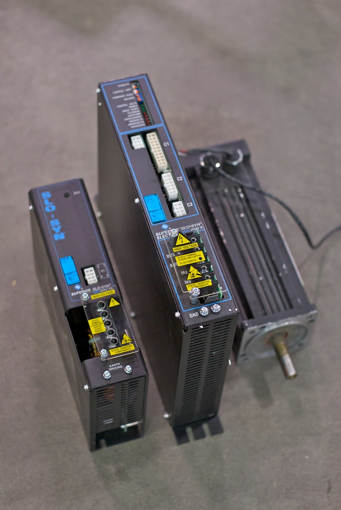
This might be the motor I use for the spindle. Kollmorgen AC Brushless, Resolver feedback. About 1HP. 1900RPM max. The drives are Superior Electric Slo-Syn SS2000 drives. Analog input. The smaller unit is the power supply that runs the drive. It provides buss voltage and logic power. Its awful bulky so I am not sure. Again, too big of aperture so lack of depth of field.
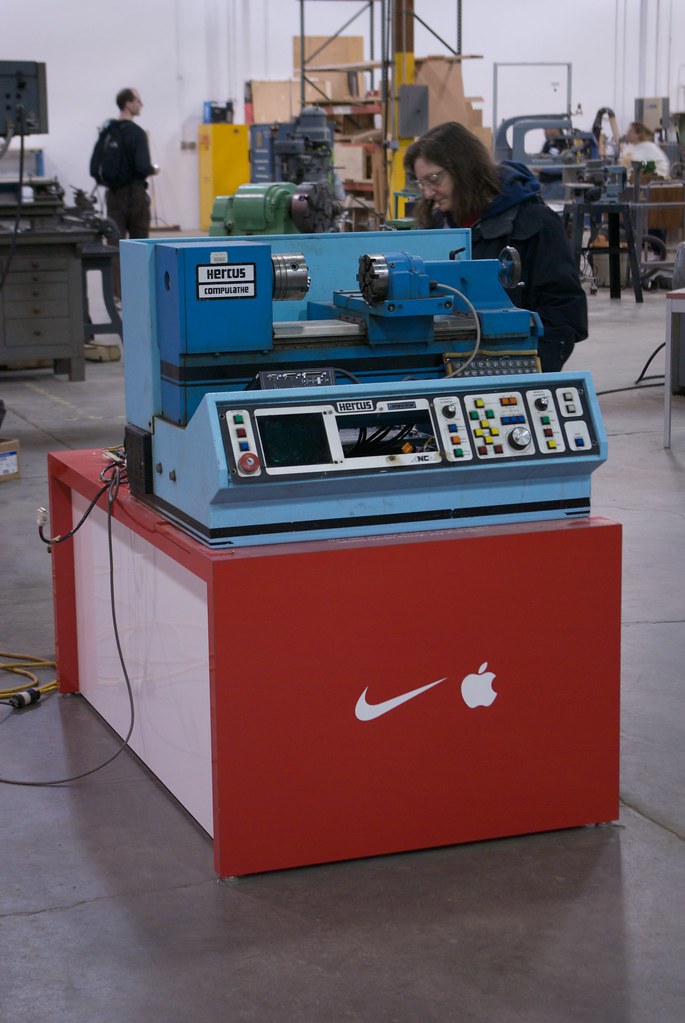
Took apart the tool turret as well tonight and figured it out. Really neat mechanism and very well made. The housing is cast iron. Where the turret rotates the bearing surface is hand scraped. The turret is pretty simple to control. Runs off 24v dc. Two wires for motor. three internal microswitches. One senses turret locked, one senses home and one senses each position. The way it operates is this. Power is applied to the motor to make it turn clockwise looking at the face of the turret. The shaft turns gearing which pulls a conical pin back that unlocks the turret. The turret is now rotates clockwise. When the in-position switch closes the control stops the motor and reverses it. This causes the conical pin to seat which locks the turret in place and also brings it into alignment. The lock microswitch closes and tells the control to turn off the motor. The home switch in the turret activates when tool #8 is in position.
Should be real easy to make work. Just a little h-bridge chip and a little micro controller. Maybe something like the arduino that everyone is talking about.
My friend managed to figure the pinout on the keyboard. Looks like everything maps to pretty much normal ACSII on the 8 bit parallel output. Might try one of these Teensy micro controllers to get the computer to see it as a normal keyboard. http://www.pjrc.com/store/teensypp.html Supposedly there is info how to make windows treat it as a HID USB device.
5/1/09
I think I have figured out what I am doing for the spindle now. I have a compumotor 750w brushless motor that will fit in there if I modify the amphenol connectors that connect the encoder and motor power leads to the motor. The drive that was intended for the motor is toast and the one I hoped to use with it dosnt have the voltage to run the motor at anywhere full power. The motor needs 240v and the drive would only put out about 120v.
So I found a Glentek drive on ebay that should do the trick:
http://cgi.ebay.com/ws/eBayISAPI.dll...m=330323927179
I still need 240v for the motor so I am going to use the transformer that was in the machine to up the 120v to 240v. Hope the transformer will be enough.
I got the X axis Servo mounted today. Took a bit of figuring. Milled out the existing mount to drop the centerline of the motor lower and made an adapter plate to mount the new servo to the old servo's holes. It all still fits in the old box. Need to order new pulleys now and figure out the belt length needed.
http://farm4.static.flickr.com/3361/...24f26eee_b.jpg
-
07-11-2009, 09:34 AM #5
Registered
- Join Date
- Apr 2006
- Posts
- 158
5/15/09
Made some more progress on the lathe in the past couple weeks. The connectors for the servo motors showed up. I build a heatsink to hold the drives and made ducting to get air moving through them. Got the power wired up to the drives. Bad news. One of the drives is bad. When I first hooke up power everything seemed normal. But when I enabled the drive it started running without an input. Not good. Disconnect and reconnected the drive and now its pretty much dead. All the lights come on and stay on. No response to the computer either. The other drive works fine though, even with the same cables and motor. This sucks...
But I have a couple mitsubishi drives and motors. One 200w and one 400w. So for now I am going to use them even though the 400w is way overkill for the Z axis. Thats over 1/2HP.
I also got the glentek servo drive running with the compumotor motor I have. Had to adjust the timing of the encoder to get it to commutate right though. Now it seems to work good. At 208v input it runs at about 2900 RPM and on 240v it runs at 3200 RPM. Belted to the spindle thats about 3300RPM max in high belt and 1200RPM max in low belt. Incredible starting torque. Spins up in a fraction of a second.
The pulleys showed up from SDP-SI yesterday. Machined them out and got them mounted. Had to figure out how to mount the new spindle motor. The power and encoder connection are large amphenols and with the motor mounted to the original mount the connectors fell smack in the middle of a bed rib. So I needed to move the motor back about 3/4" to clear the rib. Took the old end bell off the old motor and used that to make an extension/adapter. Also had to extend the shaft a bit since the shaft would only pass about 1/2" into the pulley.
Now the machine is pretty much mechanically finished. Its all electrical now. Need to get a motherboard for the computer section. A BOB as well. Need to come up with a way to control the tool changer as well. Might be able to do this through Mach with a "brain".
I have also decided to run the thing on 240v instead of 120. The new spindle drive needs it for the motor. Even if I used the old motor it still needed 240v to run the correct drive for the motor. Unfortunately the Mitsubishi servos I have are 100-120v in, not the normal 240v so I found a couple drives off ebay. I will use the 400W until I can find a 200 watt motor and drive to replace it.
I did disasseble it and clean it up. Looks a lot better. There was still bluing under the headstock where they scraped it into alignment with the bed!
I cant imagine how much this machine must of cost when it was new. There are three resolvers in the machine and those things sell for $1500 each nowadays.
New Drive motor:
Backside with new X axis motor and new cable guide.
-
07-11-2009, 09:35 AM #6
Registered
- Join Date
- Apr 2006
- Posts
- 158
5/24/09
There is mention of a version of the machine with coolant capability. That must be the one you have. I may add a spray mist unit to it. I have another Bijur unit sitting new in the box.
Made some progress on the lathe in the past week. Got all the limit switches and tool changer switches wired up to a bank of relays for isolation. Got to thinking about it and added three more relays and now have the tool changer fully controlled by relay logic. Two inputs, one sends the turret to home position and the other indexes it one position at a time. Really quick changer. About a second from tool to tool.
Got the two 200-230 versions of the Mitsubishi drives off ebay and wired them up. Both work good. I can jog the axis's via the built in control panel. Also got the spindle drive mounted and wired in. Hooked it to a cnc4pc C6 step/dir to analog speed control board that used to be in my mill until I installed one of Peter Homanns Digispeed boards.
Now I am waiting to get paid so I can buy a motherboard to go in there. Also need to figure out what I want to do for a breakout board. I think I can do all the IO on one parallel port since I am going to use a PoKeys 55T for the control panel interface.
A friend who works down at FEI may be getting me one of the old miniITX boards they use in their electron microscopes so that may solve my mobo issue.
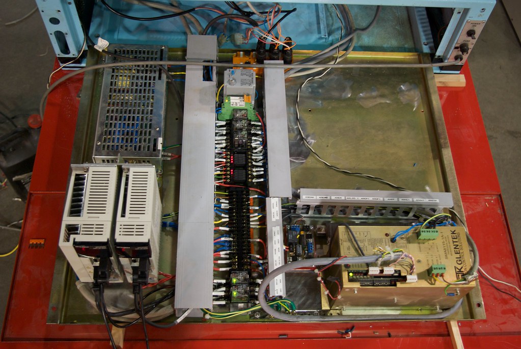
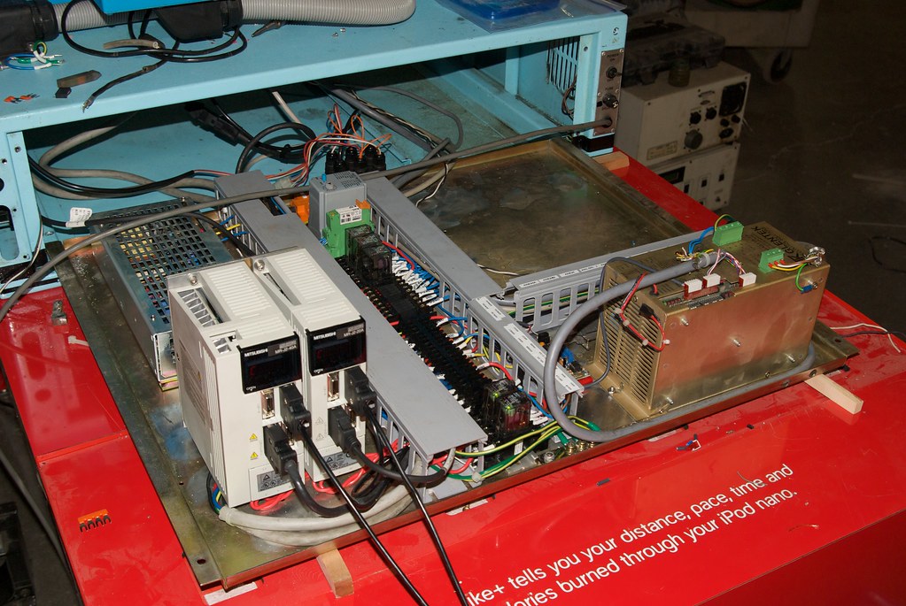
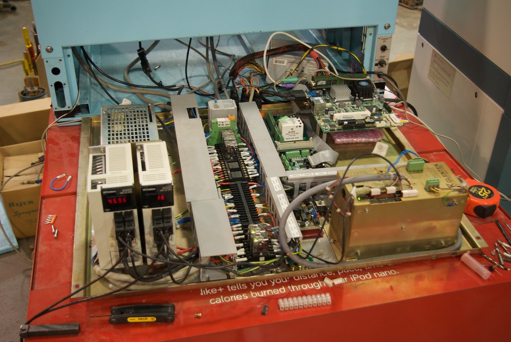
Heres a couple pics of it so far. Axis drives are in the bottom left, spindle drive with its control in the bottom right. Relays and terminal strip down the center. +24v/12v/-12v/+5/-5v power supply top left. Top center is the limit switch breakout. Open area is where the mobo and breakout board will reside.
-
07-11-2009, 09:38 AM #7
Registered
- Join Date
- Apr 2006
- Posts
- 158
7/1/09
Finally made some progress on the lathe. Bought a Tyan S3095 motherboard for the machine. Its a FlexATX form factor board. Supports anything from Pentium M to Core2Duo in a Socket 479 package. I happened to have a 1.66Ghz CoreDuo processor in that package so I went with that. The board itself has built in compact flash, 3 ethernet ports, PCI, MiniPCI, PCI-E 4x, USB, serial, parallel, firewire, and LVDS for a direct connection to a LCD panel. I am currently running the system off a 5GB compact flash micro hard drive.
I got a neat little LCD screen that I am hoping to get working with the LVDS on board the MoBo. Its a little Toshiba 5.6" LCD. 1024x600, 18bit color. Darn well need a magnifying glass to read it! I will have to get an adapter to use it though. The connection on the panel is one of those flex circuit connections. Found one company that makes an adapter to standard LVDS connection.
Ordered a PMDX-122 breakout board. Did some figuring and can run all the major timing critical I/O off of a single parallel port. The board handles charge pump and has an relay to control my spray mist unit. The rest will be done with a PoKeys55 and a ModIO. Peter Homann in Australia is writing a macro for mach3 to control the tool changer with his ModIO board. He really has some well made products.
Last I got a 8 position Opto22 board to control IO to various things.
Yesterday I got the spindle running. Not without issues of course. The darn thing would run faster in one way than the other. Made no sense at all. Checked the encoder timing which was fine. Finally found that the voltage to the drive was different in fwd vs rev. I am using the differential input on the servo drive to control forward and reverse. +10v on one input is full speed CW, +10v on the other is full speed CCW. A relay on the step/dir to analog board switches between the two. I checked the impedance on the inputs of the drive and found one was 19k and the other was 31k. The difference in load was causing a variation in the voltage drop out of the frequency to voltage converter on the board. Added a resistor and fixed that problem. Did some tuning and it seems to work fine. Max spindle speed of 3400 RPM.
Today I got the thing moving. More issues though. Tried yesterday and got no results. Did some research and found a post saying they want 24v inputs on the step and direction inputs. So I made up a little board with a ULN2003 to give the drive 24v pulses from the 5v out of the breakout board. Hooked it up. Smelled something hot! And it was coming from the servo drive!
Opened up the drive to find a burned up surface mount resistor that was in series to the optoisolator. Not good. Luckily I had another drive to compare the circuit to and was able to verify nothing else was bad. Replaced the 91ohm resistor with a non-surface mount variety and tests match a new drive.
So what the heck was wrong? I start looking through the manual on the drive. They are inputting 24v though the on board supply. They show it internally feeding the optos through a 1200 ohm resistor in single ended mode. They also show the resistor, although unmarked, in the differential line driver mode. But the drive and the schematic do not agree. The unmarked resistor in the picture in the line driver schematic is actually the 91 ohm resistor, not the 1.2k resistor in the single ended schematic. Next was the hookup diagram was backwards of what it should be + was marked - and vice-versa. So I ditched my new driver board and swapped the connections on the plug on the drive and wired it up and it moves! Turns out the issue yesterday was because of polarity. When I hooked 24v to the input it dumped way too much current through the reverse polarity protection diode on the board and fried the resistor.
So I got the motors up and calibrated. Runs at about 350IPM max. Everything looks good. The Z axis screw is a bit noisy though. Will have to keep an eye out for a new one. Wired up the limits and estop circuity tonight and everything seems to be working as it should.
Tool changer is next. Need to order one of the ModIO boards. Then I need to get the front panel finished. Need to set up things like soft limits too.
Heres a couple pics of the mess so far.
-
07-31-2009, 05:37 AM #8
Registered
- Join Date
- Apr 2006
- Posts
- 158
Made a little more progress. Got spindle feedback working. Had to use a one-shot timer board to lengthen the index pulse coming out of the spindle encoder to something that the computer could see.
But the bad news is the spindle drive sucks. Very little torque under 1000 RPM. I think it may have something to do with the simulated tachometer system the drive uses to work with motors that do not have tachs. So I picked up an Allen Bradley 1398-DDM-009. That ought to do the trick and will allow me to get rid of the step/dir to analog board. I will have to buy the software to configure the drive from AB. What a pain...
Heres a video of it so far. Spindle speed 3000 RPM. Still waiting for the ModIO board from Peter Homann.
[ame="http://www.youtube.com/watch?v=V1HZibQhhWU"]YouTube - Hercus Compulathe[/ame]
-
07-31-2009, 12:22 PM #9
Registered
- Join Date
- Jul 2003
- Posts
- 62
Hi Macona
I am very interested in your conversion. I actually have a later model sitting instorage that has done no work at all which I want to convert to a modern controller as well. Mine also has the tool changer option as well
My machine I would say only went through the demo and sat ever since.
I also noticed how well they where built.
Regards
Rob
-
07-31-2009, 08:14 PM #10
Registered
- Join Date
- Aug 2008
- Posts
- 573
Macona,
You're making a really fine job of that
BillBill
-
08-06-2009, 07:24 AM #11
Registered
- Join Date
- Apr 2006
- Posts
- 158
Thanks guys. This thing is taking me way longer than I thought it would. And this is not the first machine I have done! I think it has a lot to do with me trying to keep everything as original as possible.
Got the Allen Bradley 1398-DDM-009 end of last week. This last weekend and week I installed it after I managed to find the setup software. Got it wired in and it got it right the first time! Spent a few hours tuning it and now have mach controlling the spindle by step/dir pulses. A couple little glitches here and there though. Beats the heck out of that glentek drive though. I will have to give that drive a try on another motor I have. I have a 1.8kw motor with a electronic tach out so that should make the drive happy.
I did find I am going to need the active shunt module for the drive so I can get the spindle to stop faster without tripping an overvoltage alarm.
Got the ModIO and have it installed. Hope to get the toolchanger going next week.
-
08-26-2009, 11:32 PM #12
Registered
- Join Date
- Apr 2006
- Posts
- 158
Got the tool changer going. Used a ModIO from http://www.hommandesigns.com and Peter made custom firmware to drive it.
Here it is cutting 6061 and making a 1/2"-13 thread. Sorry about the focus going in and out. The camera will not turn off auto-focus in movie mode.
-
09-10-2009, 01:21 AM #13
Registered
- Join Date
- Aug 2005
- Posts
- 828
Very nice build!!!
Are you running the X Z drives from the P Port?Dennis
-
09-12-2009, 07:47 PM #14
Registered
- Join Date
- Sep 2004
- Posts
- 412
CNC lathes are soo cool. I'm really going to have an invest the money in something like this one day.
Good Job.
-
09-20-2009, 08:08 AM #15
Registered
- Join Date
- Apr 2006
- Posts
- 158
Made quite a bit of progress since the last post. Got spindle indexing working. I am currently using the index pulse out of the 2500 line encoder through a 555 one shot timer to get a pulse length long enough to trigger the opto22 input module. A EE friend of mine came up with a little circuit that will divide the output of the encoder by 625 and give me 4 pulses, one longer than the rest to allow me to get better speed indication at low speeds. I need to make this board and install it.
I got the ModIO board from Peter Homann and after a few firmware revisions I now have a fully working tool turret on the lathe. The ModIO also displays the current tool position on the back of the machine with a Omron LED display.
I have the auto oiler installed and working. It was kind of a pain since Mach has no way to trigger a pulse on home. The bed of the machine has oil ports drilled in the v-ways where the carriage ways are resting at home position. The cross slide has ports to lube its dovetails as well when it is in position. I had a Robertshaw Oiler I picked up from Boeing when the surplus store was still in operation. It is adjustable to run in a couple different modes. Timed run with time interval. It also has a mode that allows it to count pulses. You set with a dip switch how many pulsed to activate at and when you hit that on the pulse it runs for a set time based on the other dip switch in the oiler. It puts out over 100psi and have ruined a couple gauges before I figured that one out!
The Bijur mister is working as well. It is controlled through a SSR in one of the Opto22 module slots. Amazingly enough the pinouts were right on the SIP style SSR and I just had to bend the leads to fit in the sockets. I am using Koolmist 77 as my coolant, the same as on my CNC mill. I picked up the Bijur unit NOS from Plaza Machinery for $50. He also threw in a Noga misting unit which I was able to modify to connect to the Bijur Unit.
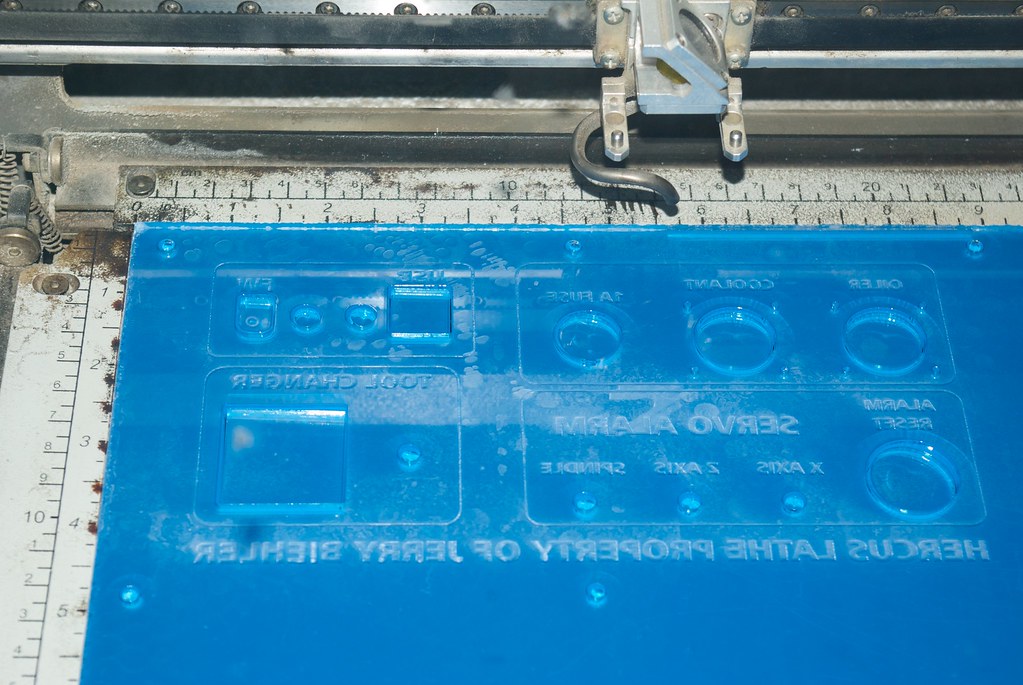
To connect the machine to the outside world I made a back panel out of acrylic on our Epilog laser cutter. Made out of 1/4" plexi and laser etched the graphics on the back side. Filled in the markings with dry erase marker and then painted it Sun Yellow with a rattle can. It is mounted in a square hole plasma cut into the back panel.
I finished wiring up the servos and spindle drive. Now if any of them fault it will trigger the machines E-stop circuit bringing everything to a rapid stop. I tested it, it works. When I was parting a piece of aluminum the piece flew off and jammed between the turret and the chuck jaws jamming the spindle. The drive faulted and stopped everything. I have also tied all the reset inputs to one oushbutton switch on the back panel. Also when any drive or the turret faults there is a corresponding light on the back panel that illuminates "MALF" when it happens. Had to build a small board to control the lamps. I wanted to isolate the drives from each other so I used opto couplers to control the lamps and the input for the oiler. Of course the lamps pulled more current than the optos so I had to add a 2N3904 to drive the lamps.
Also on the back is firewire and USB as well as the connectors and fuse for the oiler and mister. The power for these is provided from a little 220 to 110 v transformer since the machine runs off 240. Right now the whole thing is running on a pretty massive 120 to 230v isolation transformer I pulled out of a LASIK machine. Power to the everything but the computer is triggered by a Omron SSR that is driven off the 5v rail on the computers power supply.
I had some issues with the spindle drive tripping overvoltage warnings on me during deceleration. I talked with a friend or mine who designs servos drives and decided that adding input capacitance to the main buss should be enough to absorb that regenerative surge on deceleration. It did and now I can stop about 3 times faster without faulting. This also allowed me to tune the drive much more aggressively.
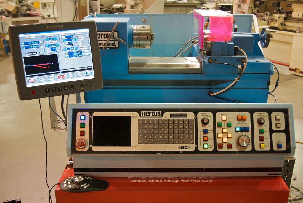
I made a chip guard from acrylic based on what was left of the original. Used whatever I had laying around which was a bunch of fluorescent plastic. Laser Etched a "Crush Zone" waring on the front of it.
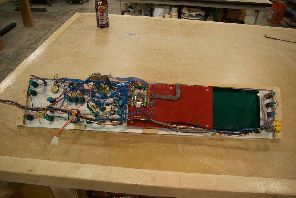
I am starting to get the front panel wired up got the power switch and reset for the computer as well as the E-stop button on the front panel. The lamps on the panel are telephone slide style lamps, not the common T-2 style but the more expensive T1-3.4 style. For the lamps on the power and reset I removed the glass bulb from the slide and replaced it with a LED and resistor. I ground the lens off the front of the LED to give a better spread. The power button lights up on power and the reset is connected to the mainboard's HDD indicator output. For most of the panel I will be able to use the existing lamps which will be ran off 24v from the main power supply. I have brought up power to the panel with a molex as well as the wires to trigger a manual tool change. The rest of the board will be controlled by a PoKeys 55 USB interface.
Tooling has been a pain. The tool holders are clamped from the bottom of the tool holder with a taper lock. I have found that the top hard stop of the tool slot is ~.070 lower than the center line of the lathe so I need to mill or surface grind the top of the tool holder off.
Heres the back panel in the laser cutter:
Pic of the mostly finished electronics:

Front of the machine:
Back of the machine:
-
09-20-2009, 08:09 AM #16
Registered
- Join Date
- Apr 2006
- Posts
- 158
Yep. Support seems to have died for the smoothstepper and there is still no backlash comp available. Until that happens I am using the parallel port. Everything is done with a single parallel port, well, and a serial port. Originally Posted by DennisCNC

-Jerry
-
10-29-2009, 06:58 AM #17
Registered
- Join Date
- Apr 2006
- Posts
- 158
Almost done! The front panel is finished. The pokeys works really good. The keyboard matrix function works great. I pretty much used up every IO on that board. The MPG does not work great. They are working on that. I was going to relamp the panel with LEDs but I decided it would be easier to just make a little board with transistor to drive the oddball mini telephone slide lamps at 24v.
The spindle speed override is still not working, same with the feed hold light. Something in mach is causing both of these problems.
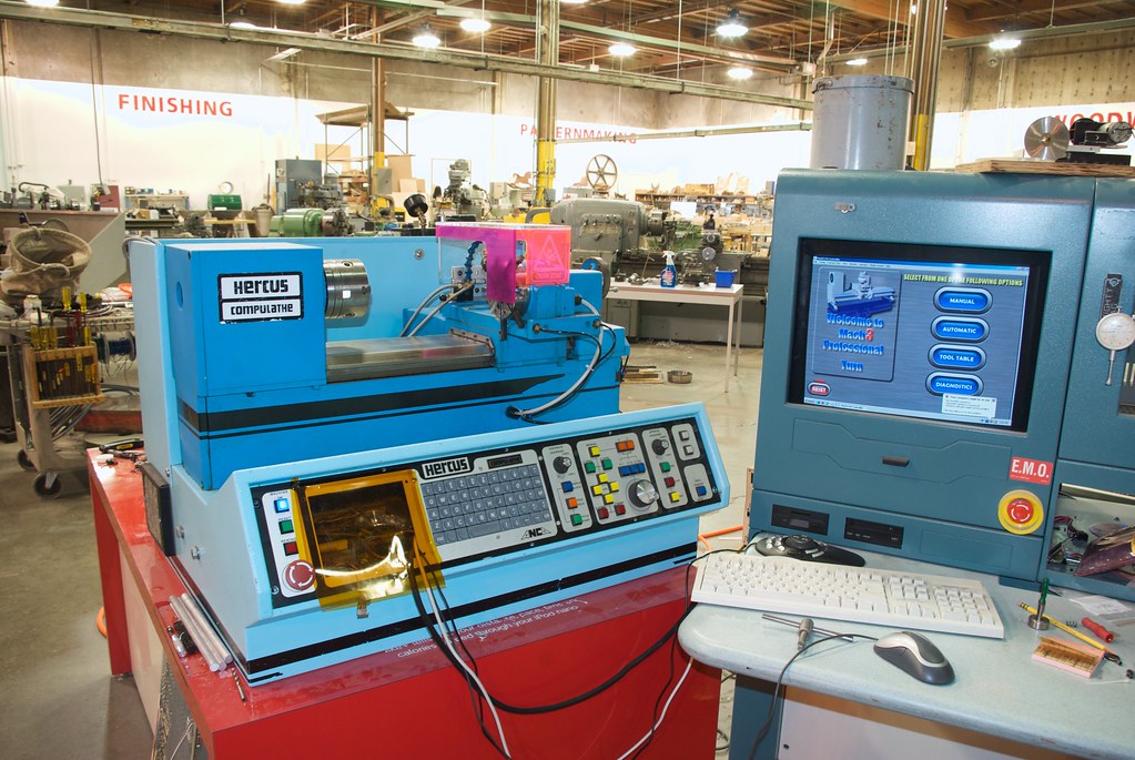
Have the display mounted to the side of the machine. Used a Anthro flat panel mount and made a support for it out of acrylic on the laser cutter.
Now I just need to mount an external antenna connector on the back. The mini-pci wifi card has a tiny little rf connector so I need to get an adapter for that.
One thing I did change on the lathe is the cooling. They had a fan on each side, one blows in, one out. I changed it to both pulling in to the cabinet. I made spacers out of some scrap alder that hold the control panel 3/8" from the front so air exits under the bottom edge of the front panel.
Couple pics as usual, Back of the panel and the machine in general.
-
12-30-2009, 08:58 AM #18
Registered
- Join Date
- Nov 2008
- Posts
- 228
Hey, Wonderful log and great build! Originally Posted by macona
Could you please sketch up a diagram on how you did your tool changer logic to be so well controlled without a stepper? I have a little lathe but when I buy a 10x22 to CNC I will have a tool turret and I have only seen versions that requires a stepper and controller.
Thanks!
-
12-04-2010, 09:11 AM #19
Registered
- Join Date
- Apr 2006
- Posts
- 158
During the thanksgiving break i actually made parts with the lathe that are functional. Woo!
Here is a little video:
watch it in HD!
[nomedia="http://www.youtube.com/watch?v=L7iztfFGtyM&hd=1"]YouTube - Machining adapter on Hercus CNC[/nomedia]
-
01-13-2011, 01:05 PM #20
Registered
- Join Date
- Mar 2004
- Posts
- 1306
Excellent, well intergrated retrofit. Thanks for sharing it.
Is that your shed in the background Looks well equipped.
Regards,
Mark

 Reply With Quote
Similar Threads
-
Hercus PC200 Retrofit
By isjohn in forum Servo Motors / DrivesReplies: 16Last Post: 12-03-2015, 01:49 AM -
Hercus Computurn
By Doug Baker in forum Australia, New Zealand Club HouseReplies: 0Last Post: 04-16-2009, 04:45 AM -
Hercus ANCA CompuLathe Model : 2000LVL1
By BPRacing in forum DNC Problems and SolutionsReplies: 1Last Post: 11-12-2008, 03:37 AM -
parameters for anca 2000 hercus compulathe
By poppyplant in forum DNC Problems and SolutionsReplies: 2Last Post: 05-27-2005, 05:26 AM
