


Well guys I have been doing a lot of reading and looking at options before I decided to posted anything. I got the X2 the other day and have already assembled my controller box. I went with the Probotix 3-Axis kit with the 400oz Nema 23 motors. I have my X and Y axis planed out, but am kind of lost on the Z axis. I want to go the cheapest route for right now until I can get the ball screws for all axis. Is there a simple way to convert the Z without breaking the bank?
Thread: Seig X2 CNC Z-Axis Conversion
Results 1 to 14 of 14
-
08-13-2009, 08:19 PM #1
 Registered
- Join Date
- Aug 2009
- Posts
- 899
Seig X2 CNC Z-Axis Conversion
-
08-13-2009, 09:01 PM #2
Gold Member
- Join Date
- Feb 2006
- Posts
- 7063
I did mine very inexpensively, and it works great. I ordered the Z axis leadscrew and nut for an X3 from Grizzly, and used them, with a 450 0z-in, motor and 2.5:1 belt reducer. It has no trouble at all moving the head, with no weights, air springs, or anything else. The weight is enough to make backlash a non-issue, as long as I approach cutting depth from above. Since I'm only doing 2.5D milling, this is *always* the case, so no problem. I put the screw behind the column, using a setup almost identical to that on a stock X3, by bolting plates to the sides of the head, and one behind the column to hold the nut. I did the whole thing in barely a day. The screw and nut were ridiculously cheap - I think about $30 for both, IIRC. the screw is at least 3/4" diameter, 10 pitch. Originally Posted by eartaker

Regards,
Ray L.
-
08-13-2009, 09:34 PM #3
Registered
- Join Date
- May 2007
- Posts
- 767
Hi
I am about to start cutting metal for a CNC conversion to my X2 look alike mill. Like Ray I have opted for a screw on the back of the mast and whilst I am using ballscrews for all axis the design would work with any type of screw. From some work I have just done using M15 roll threaded studding from my local hardware store I think even that would work over the 200 mm or so required for the Z axis particularly if it is only being used to raise and lower the tool in Z for 2D machining in X&Y
The cheapest bearings I have found to date are the double row angular contact type and for the three I have purchased the axial end float unmounted is non existent and mounting them will of course further increase the preload. (Do a google search for your local supplier of bearing 5201RS 12mm bore x 32mm OD x 15.9mm wide. Mine cost me £8.25 each.)
The two files are of an early GA of the Z axis complete but I changed my mind several times so the bearings appear distorted and date from when I was going to use separate thrust and radial ball races. Discovery of the 5201 bearing changed my mind as it is simple to machine the required housing! Also the cost is about the same as a skate bearing and a thrust ball race. The other file is of the motor mount I am going to make for the Z axis. The X and Y will use the same mount as it is easier to keep them all the same and make them at one session.
Hope this helps with the planning.
Regards
Pat
-
08-13-2009, 09:44 PM #4
Member
- Join Date
- Apr 2006
- Posts
- 8159
Chuck and will_eng did some very cheap Z conversions on their mill. Originally Posted by eartaker
Temporary at best but that's what you seem to be looking for till you can go with a proven version like cncfusions.
No need to build something monstrous, simpler the better.
Hosshttp://www.hossmachine.info - Gosh, you've... really got some nice toys here. - Roy Batty -- http://www.g0704.com - http://www.bf20.com - http://www.g0602.com
-
08-15-2009, 09:13 PM #5
Registered
- Join Date
- Aug 2009
- Posts
- 899
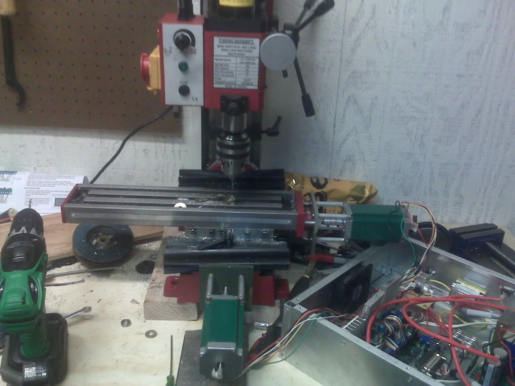
I think I have a work around for now. I am leaving the mill intact without adding any leadscrew. I have put a 20 tooth gear on my motor and an 50 tooth on the fine adjustment shaft for the Z-axis. I am close to having it all mounted and will let you know how it goes. If any of you have tried this let me know how it worked for you.
-
08-15-2009, 09:35 PM #6
Member
- Join Date
- Apr 2006
- Posts
- 8159
Chuck and will-eng linked to above made use of the fine feed making use of the worm drive.
Backlash will be a big issue, I take it you are not using the worm drive so that should be a bit better.
Post some pics when you're done please.
Hosshttp://www.hossmachine.info - Gosh, you've... really got some nice toys here. - Roy Batty -- http://www.g0704.com - http://www.bf20.com - http://www.g0602.com
-
08-16-2009, 08:25 AM #7
Registered
- Join Date
- Aug 2009
- Posts
- 899
No Hoss I was planing on using the worm drive but I would have to compensate for a lot of backlash. I think if I keep a constant pressure on the worm drive that I can eliminate the backlash to almost none. I will probably use a counter weight of some sort and remove that useless spring.
-
08-18-2009, 02:33 PM #8
Registered
- Join Date
- Jun 2008
- Posts
- 165
My first down-and-dirty Z axis actuator was simply to put a big timing pully on the pinion and a small timing pully on the stepper and mount the stepper on a simple flat piece of 1/4" aluminum plate bolted to the side of the head with the motor behind the column.
I still have the big pulley and belt anf maybe even the small pulley. I also have a 640oz-in NEMA 34 stepper for sale. Could make you a great deal on the whole setup.
I cut up the mounting plate to use the NEMA34 part for my current setup, so you'd need to make that, but it is simple.
Using the worm is not necessary, complicates things and will be dog slow and also introduce a ton of backlash.
I'll see if I ever took a photo of that setup and post it if I have it. EDIT: sorry. no photo, but there is a side view of the geometry in .dxf format so you can lazy cam it if you want to make the mount:
http://www.thecubestudio.com/picture...ZaxisFirst.dxf
-
08-18-2009, 10:58 PM #9
Registered
- Join Date
- Aug 2009
- Posts
- 899
After looking at thing I have decided to not use the worm gear, I will use a lead screw of some sort. Just not sure of how I will set it up though
-
08-19-2009, 09:07 AM #10
Registered
- Join Date
- Aug 2009
- Posts
- 899
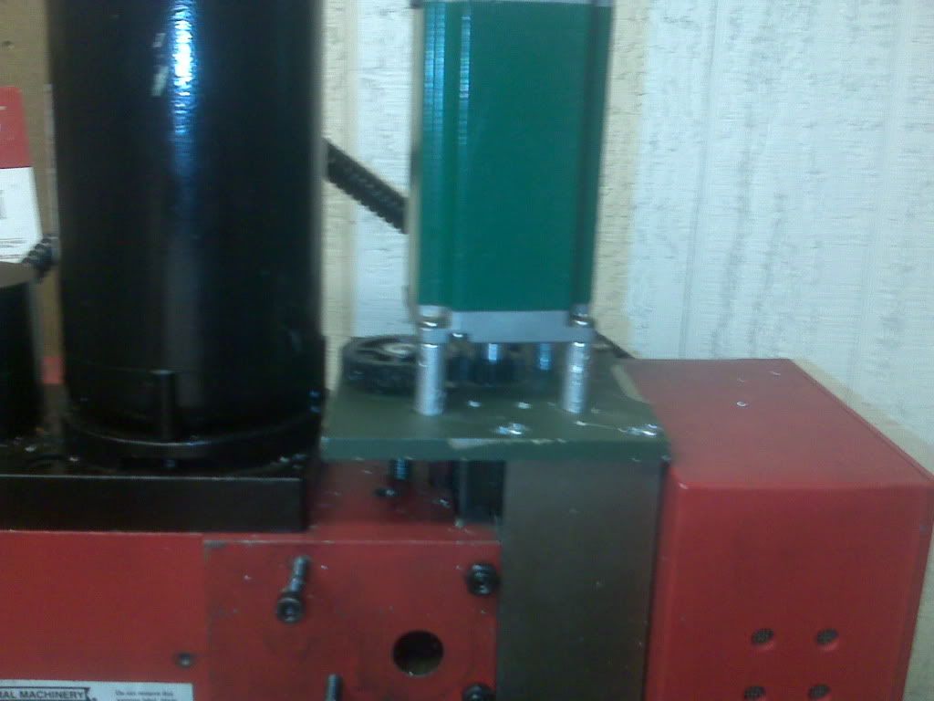
Well I went with a 3/8 16 screw with a 2:1 gear ratio on the Z axis. It is working fine and have it accurate to .001. There is .001 backlash due to the gear mesh. Have some work to do on the Y axis to make it more to my liking but as for now all I have left is wiring.
-
08-19-2009, 12:41 PM #11
Registered
- Join Date
- Jun 2008
- Posts
- 165
eartaker,
Bravo! Extremely clever temporary solution!
A lead screw on the front side of the column is ideal placement. I went from a temp solution useing the stock rack and pinion to a lead screw on the back of the column, which proved unacceptable. I redesigned to move the leadscrew to the front and it works well.
I've only recently started to participate a bit on this forum, but I see that Hoss Machine's Z axis design is very similar to mine.
I advise you develope your permanent solution along those lines.
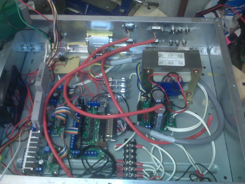
Commnets: on your control box, you may want to rerout your control cable so that it does not wrap around the transformer.
on the gears, the photos are blurry, but one apprears to be delrin. No lube needed. You can also run these gear tight at low RPM to eliminate lash. If you do use lube, I suggest a dry lube that will not collect dust or retain swarf so long as the gears are exposed.
-
08-19-2009, 05:02 PM #12
Registered
- Join Date
- Aug 2009
- Posts
- 899
Thanks, as for a permanent solution I will probably go along the same lines that I am using now but upgrade all axis to ball screws. I will probably move that control cable as well. The pic of the box isn't complete as you can see the DB-9 connectors are not hooked up and the limit switch ports are not wired as well.
-
08-20-2009, 03:09 AM #13
Registered
- Join Date
- Aug 2009
- Posts
- 899
Well here is an update, I am installing homing switches and I modded my E-stop that comes with the X2 so that it will cut power to the spindle and also send an E-stop signal to Mach 3. as for the limit switches I am lost. I cant figure out how to wire them up because the input has been used for the homing.... ill figure it out I guess.
-
08-20-2009, 01:38 PM #14
Registered
- Join Date
- Jun 2008
- Posts
- 165
The Mach manual describes how to do it. Mach can use the home switch as a limit switch.
I started out with mechanical switches, but they were a pain. Now I have all photointerruptors. Mo' better.

 Reply With Quote
Similar Threads
-
Seig X3 Conversion with Deluxe CNCFusion Kit
By MRM RCModels in forum X3/SX3/G0619/G0463Replies: 366Last Post: 10-25-2013, 09:07 PM -
Seig X1 mill - Initial Conversion Design - pdfs
By jeffo2001 in forum Benchtop MachinesReplies: 4Last Post: 02-20-2009, 02:47 PM -
BEST PRICED SEIG X2 CONVERSION PARTS?
By CNC74 in forum DIY CNC Router Table MachinesReplies: 1Last Post: 02-04-2009, 04:15 AM -
Syil/SEIG X2 CNC conversion Axis limit/home switches
By IMK1230 in forum Syil ProductsReplies: 0Last Post: 10-21-2008, 09:50 AM -
iso-30 spindle conversion for the Seig X3
By rtwas in forum Uncategorised MetalWorking MachinesReplies: 1Last Post: 04-19-2008, 03:39 AM
