


amazing stuff. was a little hard to visualize everything before, but now its all clear
whats the next step?
Thread: My CNC pressbrake build
Results 21 to 40 of 66
-
01-18-2010, 02:15 PM #21
 Registered
- Join Date
- Nov 2007
- Posts
- 197
-
01-18-2010, 07:17 PM #22
Registered
- Join Date
- Nov 2005
- Posts
- 152
I am going to build the backgauge next once I get my ball screws from A4L. Originally Posted by multiplex

-
01-18-2010, 11:34 PM #23
Banned

- Join Date
- May 2007
- Posts
- 119
Nice job you have going there !! What are you going to use for ram leveling ?
-
01-19-2010, 12:32 AM #24
Registered
- Join Date
- Nov 2005
- Posts
- 152
What do you mean by ram leveling? Originally Posted by kevin swan
-
01-19-2010, 01:34 AM #25
Banned
- Join Date
- May 2007
- Posts
- 119
left side vs right side during the stroke
-
01-19-2010, 02:03 AM #26
Registered
- Join Date
- Nov 2005
- Posts
- 152
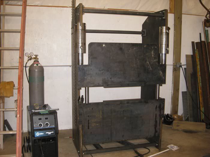
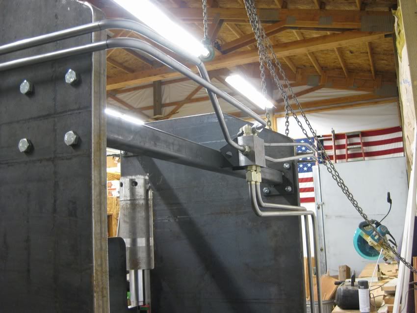
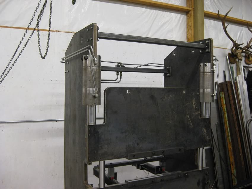
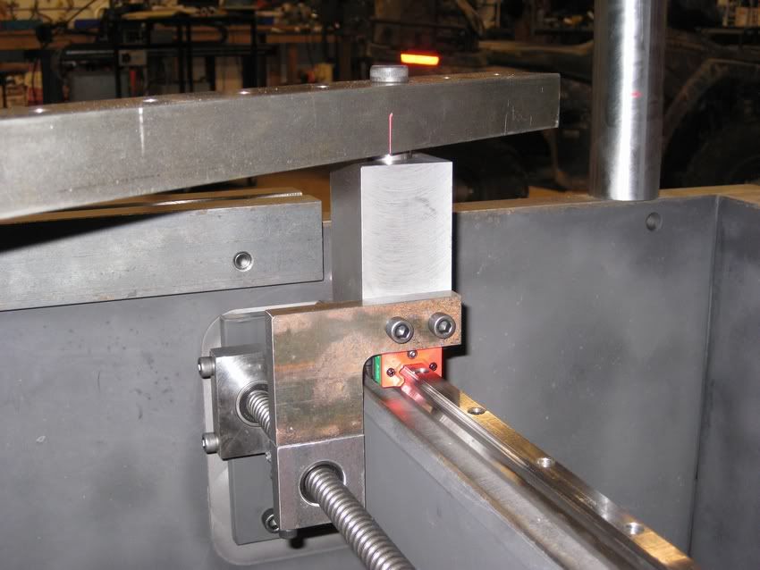
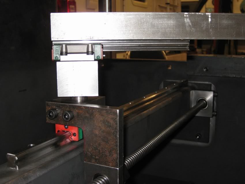
Look closer at the pics. There are 35mm Hiwin linear rails guiding the ram so it will always stay parallel. Originally Posted by kevin swan
-
01-19-2010, 02:17 AM #27
Banned
- Join Date
- May 2007
- Posts
- 119
ok sorry i missed that thank-you
-
01-30-2010, 01:53 AM #28
Registered
- Join Date
- Nov 2005
- Posts
- 152
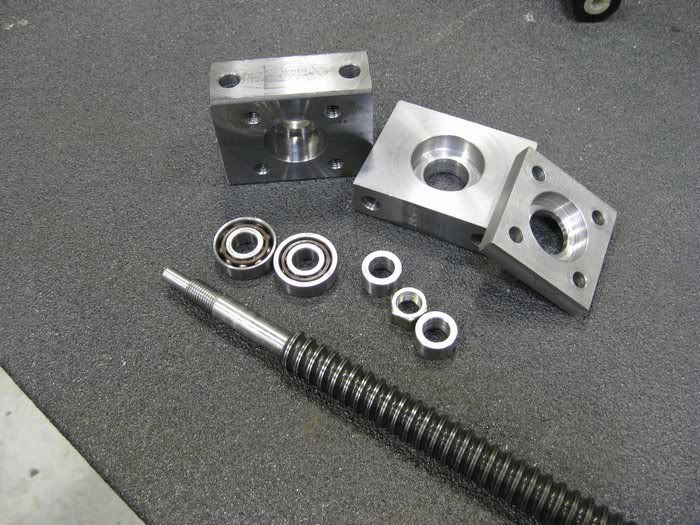
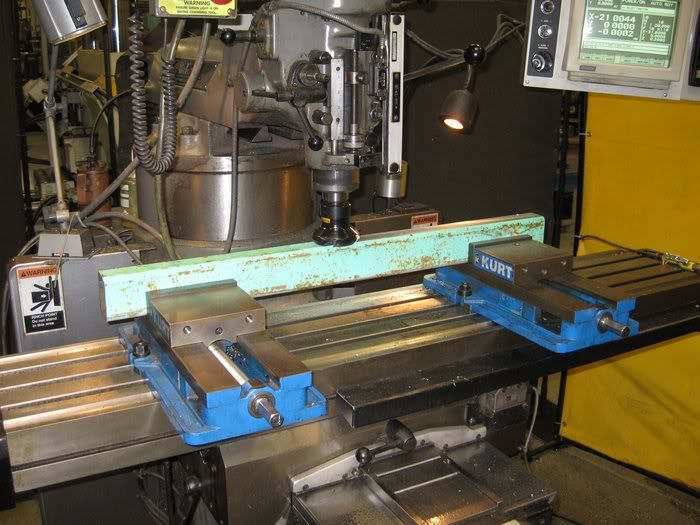
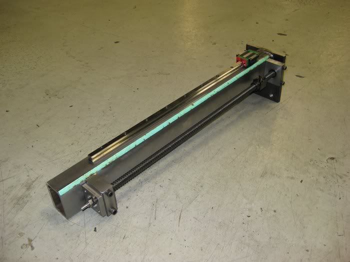
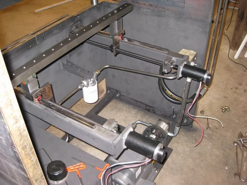
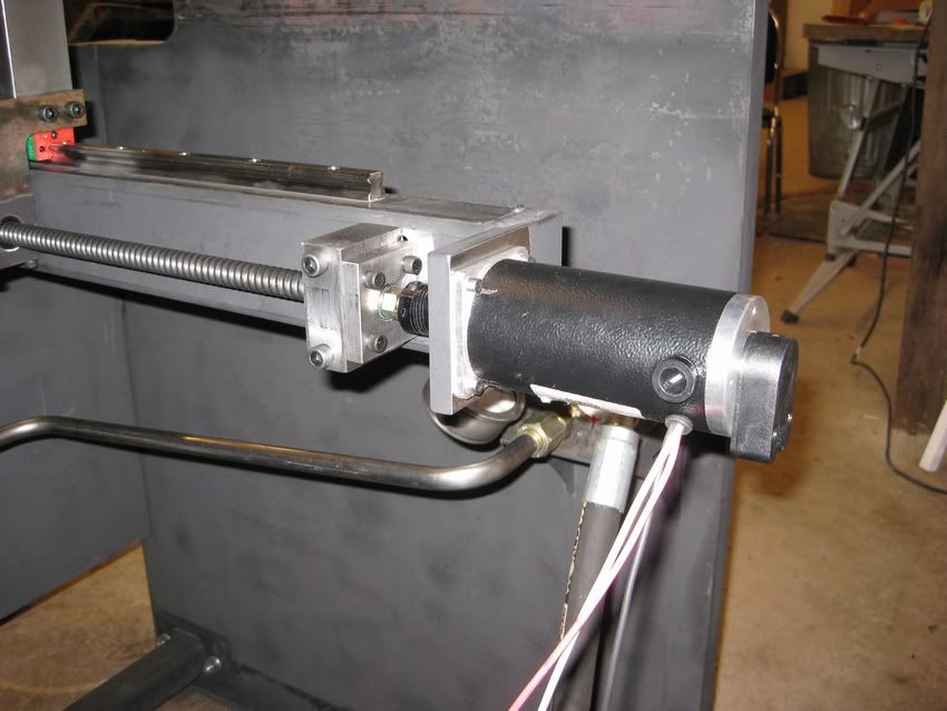
Today I got the backgage started. I machined up the ball screws and made the end supports. I also started machining up the frame for the backgauge.
-
01-31-2010, 12:55 AM #29
Registered
- Join Date
- Oct 2006
- Posts
- 669
Want to follow this, make sure I don't miss anything!

-
02-06-2010, 04:17 AM #30
Registered
- Join Date
- Nov 2005
- Posts
- 152
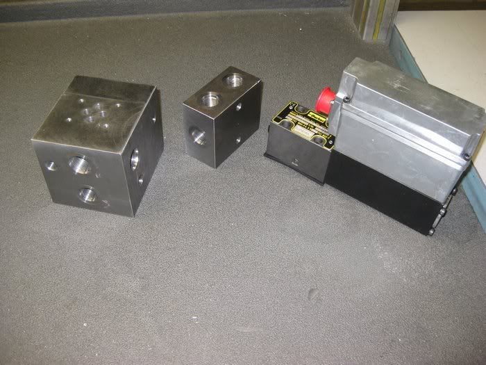
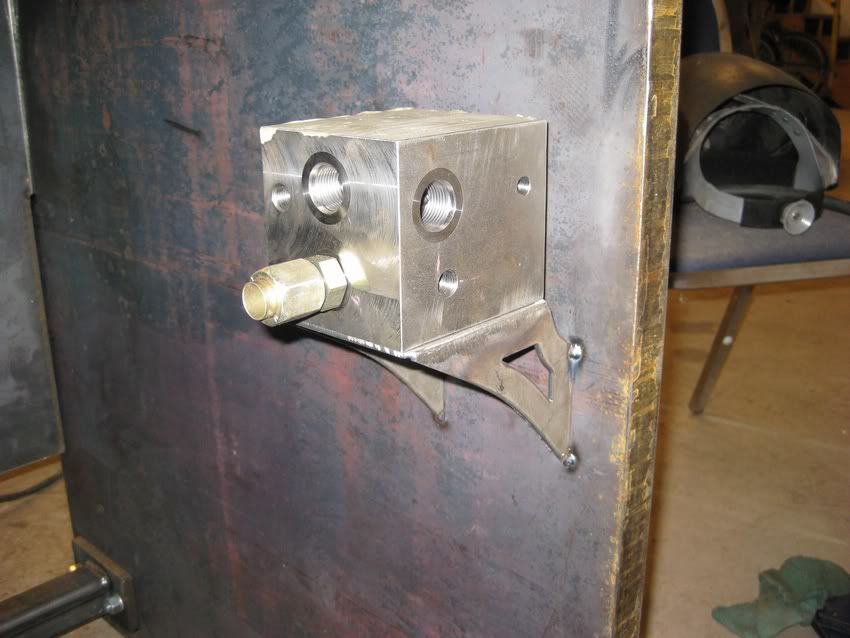
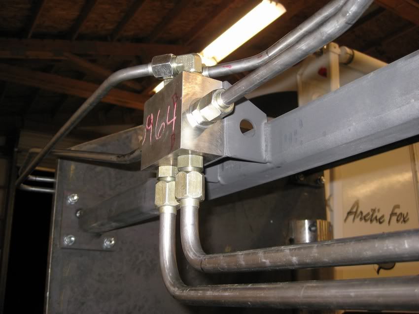
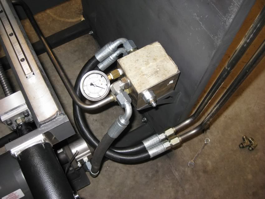
Today I got the manifold all done and also the Y block.
-
02-07-2010, 07:28 AM #31
Registered
- Join Date
- Nov 2005
- Posts
- 152
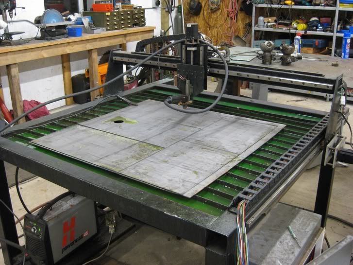
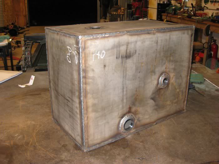
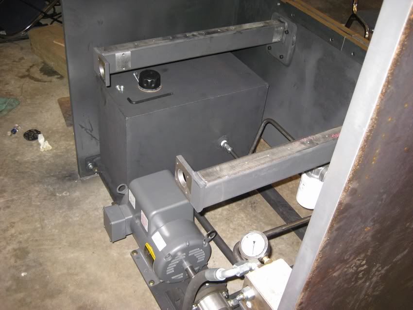
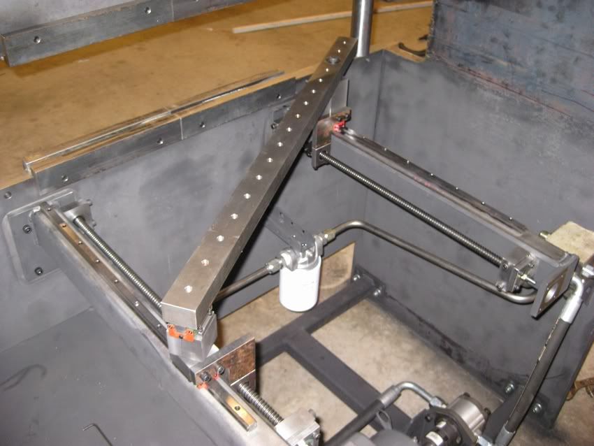
I made some spacers to hold the beams parallel. Then started to tack the cross braces into place. I also cut out all the parts for the hydraulic tank on the plas, then welded the tank all up.
-
02-07-2010, 08:18 AM #32
Banned
- Join Date
- May 2007
- Posts
- 119
looking good nice job
-
02-08-2010, 05:31 AM #33
Registered
- Join Date
- Nov 2005
- Posts
- 152
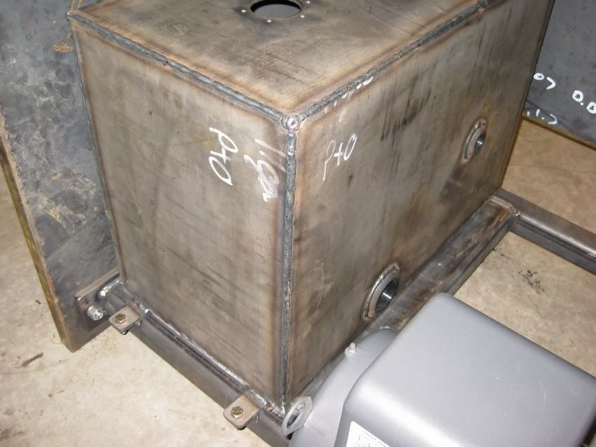
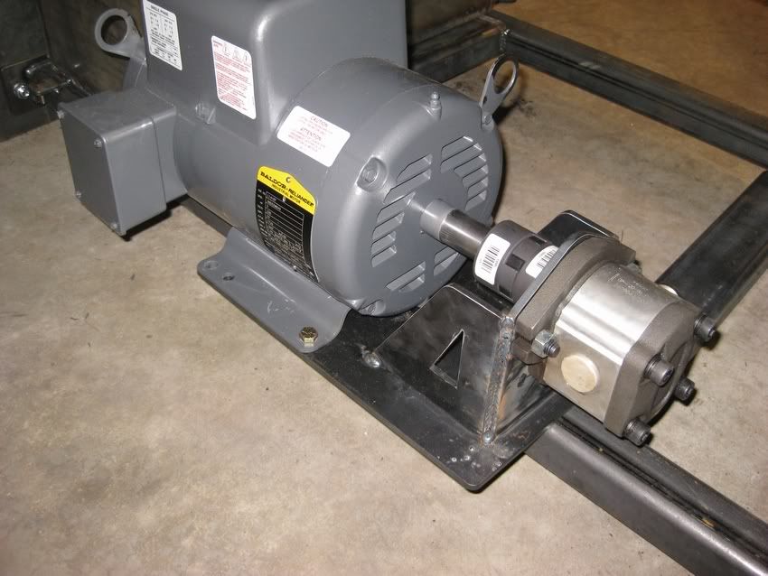
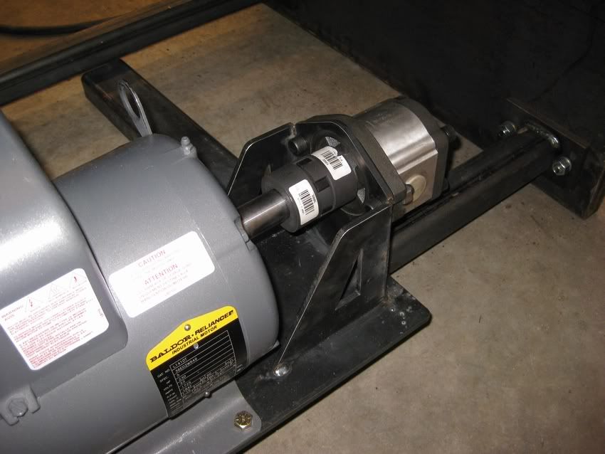
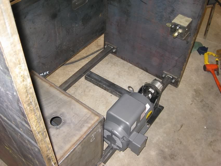
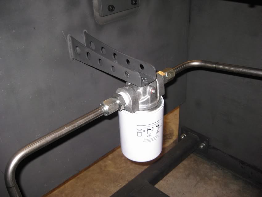
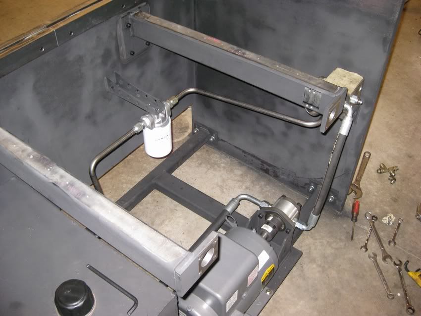
Today I mounted the tank, made the motor and pump mount and also mounted the manifold.
-
02-13-2010, 12:47 AM #34
Registered
- Join Date
- Feb 2010
- Posts
- 0
All I can say is wow!! Keep posting, the work is outstanding and it's fun to see something of this scale come together! What is the max thickness you'll be able to bend?
-
02-13-2010, 03:41 AM #35
Registered
- Join Date
- Dec 2009
- Posts
- 122
I am impressed. I've been following since you started this thread.
Some of us (including me) wish we had your talent.
-
02-13-2010, 04:17 AM #36
Registered
- Join Date
- Nov 2005
- Posts
- 152
48" of 3/16" mild steel or about 40" of 1/4" mild steel. 3/16" is about 12 tons per foot of bend with a 1.5" lower die and 1/4" is 15 tons per foot with a 2" wide lower die. Originally Posted by dirtnap
-
02-15-2010, 05:28 AM #37
Registered
- Join Date
- Nov 2005
- Posts
- 152
Yesterday I got the tank all pressure tested and finished, the backgauge all done and finished all the plumbing. I still need to finish making some support brackets for the hard lines.
-
02-15-2010, 05:32 AM #38
Registered
- Join Date
- Nov 2005
- Posts
- 152
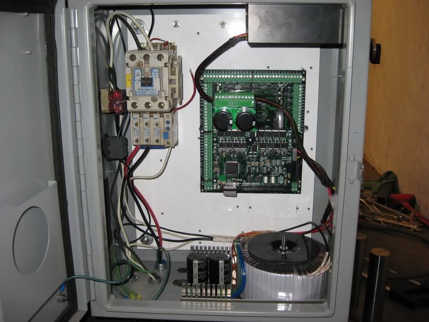
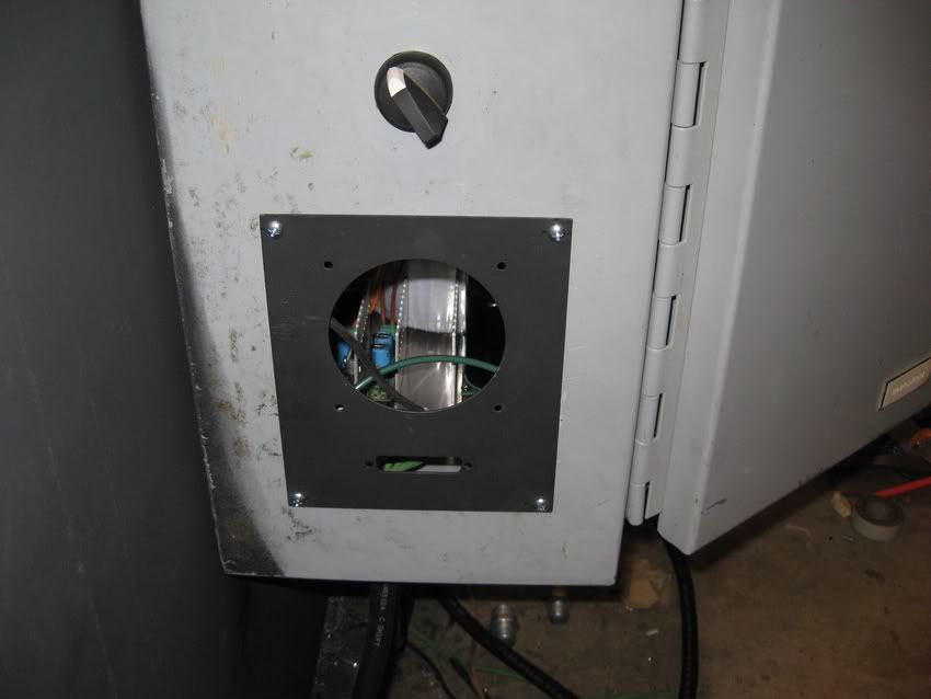
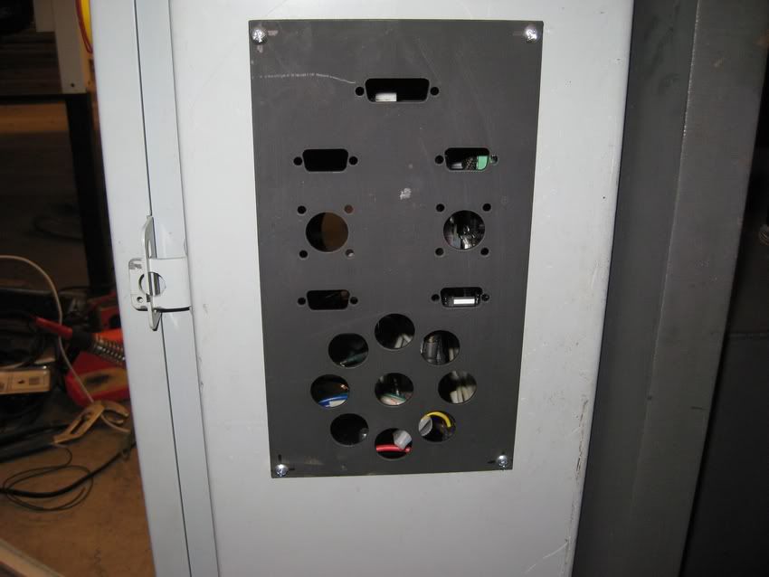
Today I got the electronics started. I mounted the control box, Wired the power supplies and the motor starter. I also cut out a front plate for a small fan and a db25 connector for the MPG. I also cut out a rear plate for the motor power wires, encoders, limits/homes switches and for the valve.
-
02-15-2010, 05:58 AM #39
Registered
- Join Date
- Nov 2006
- Posts
- 12
your project looks awesome! ive been kicking around the idea of making something similar. one question for you. how did you make sure your linear rails are parallel? i can understand them being correct looking at the machine from the front being that all that stuff was milled. but what about looking at it from the side? maybe im missing something but didnt notice anything that would keep the sides from pivoting independent of each other in a sense making the rails not parallel.
-
02-15-2010, 05:12 PM #40
Registered
- Join Date
- Jan 2007
- Posts
- 525
bigtoy - what's with the shallow-depth of green liquid in the plasma table? I'm used to seeing a water trap which is quite a few feet deep; yours looks to be a few inches...
Tormach PCNC 1100, SprutCAM, Alibre CAD

 Reply With Quote
Similar Threads
-
Yawei pressbrake type QC12Y hydraulic diagram
By zavateandu in forum Uncategorised MetalWorking MachinesReplies: 0Last Post: 08-21-2012, 01:14 PM -
LVD Pressbrake?
By rszemeti in forum Uncategorised MetalWorking MachinesReplies: 8Last Post: 07-15-2012, 10:57 AM -
delem da 65 pressbrake controller
By gerry1969 in forum Uncategorised MetalWorking MachinesReplies: 0Last Post: 03-15-2012, 05:00 PM -
Suggest me the best Pressbrake machine
By gvk1985 in forum Want To Buy...Need help!Replies: 0Last Post: 03-07-2011, 03:38 AM
