


Hey guys,
Before getting started I want to thank the owners of this forum for offering such a wealth of collective information for free. I also want to thank Leeway and Arie for their great and very detailed build threads that inspired me and helped to provide ideas.
A little background: I have a small business designing and making putters from brass and aluminum. My existing mills were both Sherlines: one CNC and one manual. Although quality mills they certainly lack in rigidity, speed and power. I was very limited in the machining approaches I could use and to a certain extent the designs possible. Plus, total cycle times were obviously a bit long.
I wanted a new CNC mill. The garage is detached, not heated or insulated and has one breaker. The basement is finished and is full of stuff. This had to be put where the existing mills were, in a bedroom. Options were very limited for a machine that would be "practical" in a bedroom, pretty much 300 pounds or less. To me, the X2 and X3 based machines had no appeal for both quality and other reasons. The Minitech that I liked was the 3 pro (With linear ways and ballscrews), but this thing was $14,000+ and looked a little light duty. It would remove material faster than the Sherline but not to the degree that would justify that amount of money. That left Wabeco, the most likely candidate. At the time it was $10,500 (Now about 9K). I would also want an ISO30 taper ($600 option) as MT2 tooling doesn't really appeal to me. The ISO30 tooling along with having a mill shipped to Canada from California would cost me a fortune.
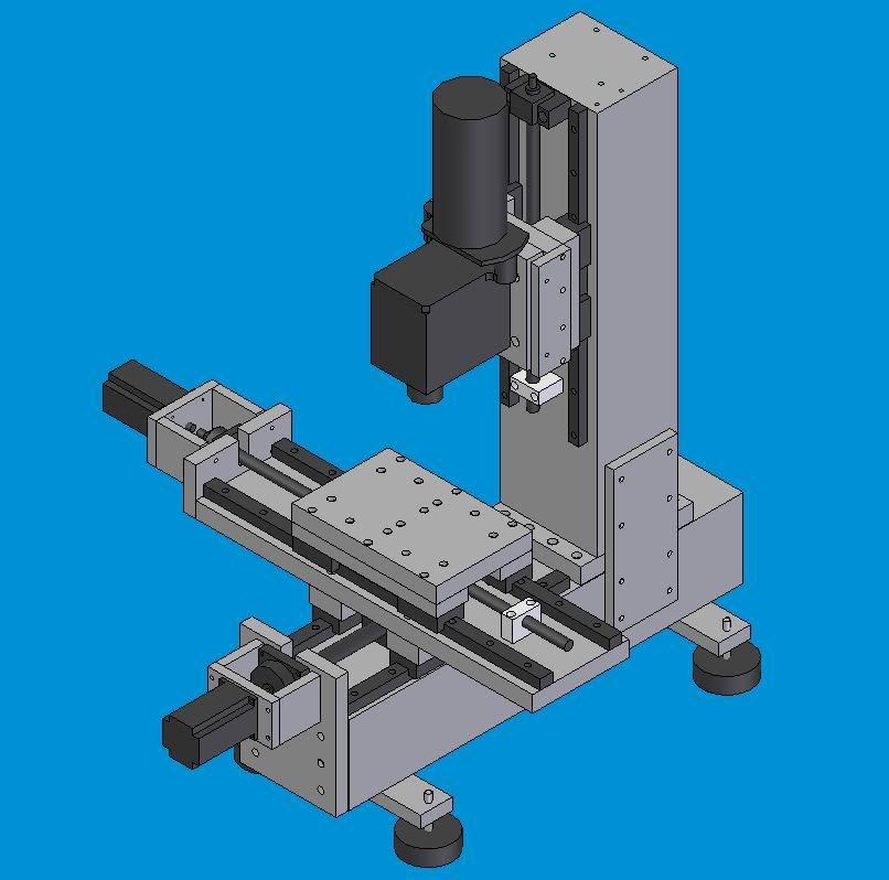
That left me with building a mill. After viewing threads on here (Lee Way, Arie, etc...) I decided on a general size and configuration. Vertical, about 11" of X, 6-7" of Y and 10" of Z, fully supported table (long saddle, short table).
The main frame components were a real problem. I didn't have much to work with, manual and CNC Sherlines. The day job is in a machine shop but time there is for them and not my projects, especially not something home business related. A bench top drill press (10" Canadian Tire one) was picked up to help me out. The only viable option seemed to be aluminum extrusion (8020 or the like) heavily cross braced and reinforced. Leeway had built quite a mill with the stuff, but he used huge linear rails for the size of the machine (25's and 35's) to strengthen it up. I started to design a mill around 8020 and then came across two 6" by 5" by 24" blocks of solid aluminum at a local scrap place. I went back, purchased one, checked it over and then bought the second. They were 70 pounds each, total cost $300.
Ground ballscrews and linear rails were purchased on ebay. The rails: 20mm for X and Y and 15mm heavy pre-load for Z, all THK. The ballscrews: NSK 20mm, 5mm pitch for Y, NSK 14mm, 5mm pitch for X, Kuroda 15mm, 4mm pitch for Z. A mill was designed around this an X2 spindle and the aluminum blocks.
Thread: DIY aluminum vertical mill build
Results 1 to 20 of 82
Hybrid View
-
01-02-2010, 05:39 AM #1
 Registered
- Join Date
- Mar 2008
- Posts
- 201
DIY aluminum vertical mill build
-
01-02-2010, 05:51 AM #2
Registered
- Join Date
- Mar 2008
- Posts
- 201
After receiving and checking over the X2 head from LMS, it didn't exactly blow my skirt up. Eight tenths of run out in the taper. Add in a Tormach collet, holder and the total runout could be terrible depending on how it stacked. Even though I had bought the belt drive conversion kit as well I decided to cut my losses instead of buying a bearing puller kit and new bearings.
Finley spindles were looked at. The price was too high ($1200) and it was a cartridge and would need an accurately bored mounting block. Plus it was ER20 so any kind of repeatable tool changes were out of the question.
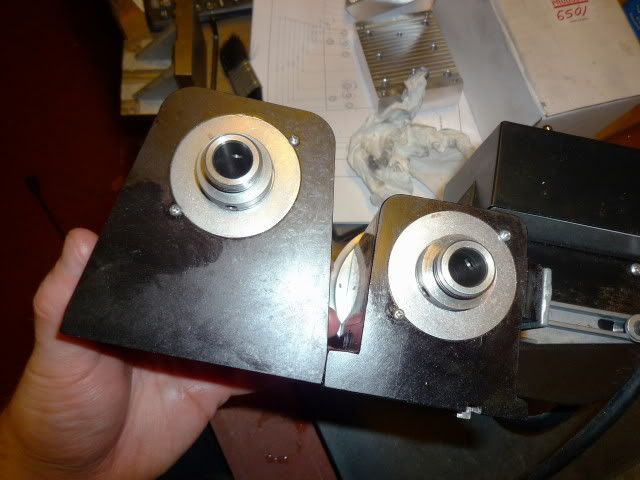
So, I checked out the Sherline industrial spindles. They had one with what appeared to be a much beefier case than the stock one. I new the shaft and bearing set were the same. But to me, the weakness in the Sherline spindles on the factory machines was in the mounting and the thin case. If a beefier one could be mounted solidly, I figured it would work quite well.
http://www.sherlineipd.com/spindles.htm
P/N 6502-3/4-16/#1 Morse spindle with 2-step "V" belt pulley
Here is a pic comparing a spindle off a Sherline mill/lathe to the industrial one. Quite a difference.
-
01-02-2010, 06:07 AM #3
Registered
- Join Date
- Mar 2008
- Posts
- 201
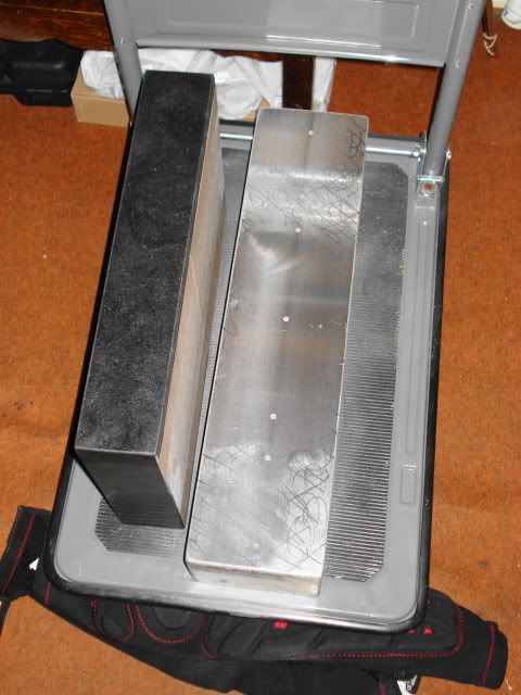
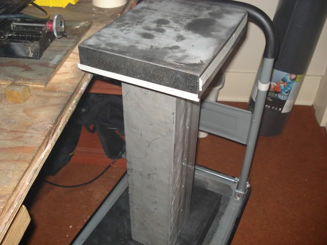
First step in terms of actual construction was the two main blocks, base and column, getting these flat and perpendicular on the important sides.
Here are the main blocks as I found them:
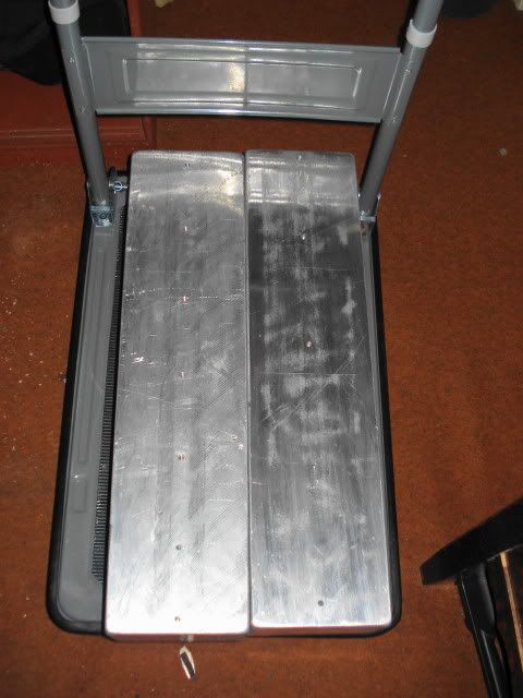
On the base block, the top surface needed to be flat and one of the ends perpendicular to this as well as flat. On the column block the top surface needed to be flat and both ends perpendicular to this as well as flat. On one block, one of the large surfaces was pretty flat. On the other, not so much. The ends on both blocks were not machined.
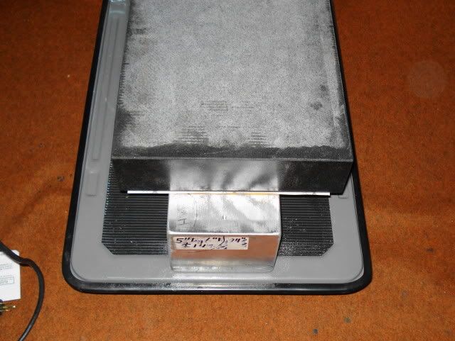
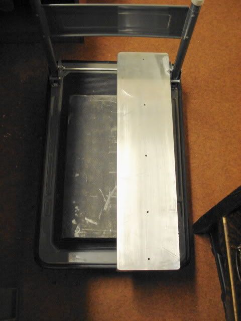
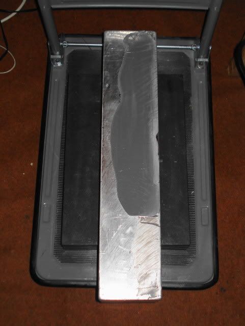
The first step was making one large surface on both blocks flat. With no mill, I decided to sand them. The whole large surface was scribbled with a sharpie. Some 80 grit sandpaper was double-sided taped to an 18" by 12" granite surface plate. The block was placed on a dolly and braced against the dresser and the granite plate was pushed back and forth over the block. The sandpaper was cleaned and the marker on the block checked every 50 strokes or so. Needless to say, it took a long time to get that surface flat (and a couple sandpaper changes), but eventually it was flat to .001" over the whole rail bearing surface.
-
01-02-2010, 06:31 AM #4
Registered
- Join Date
- Mar 2008
- Posts
- 201
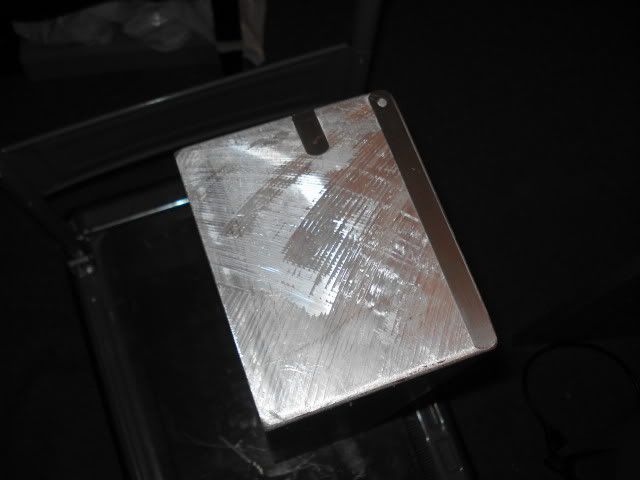
The next step provided a real challenge, how the heck am a going to get the end surfaces perpendicular to the large flat surfaces? Not only that, but one of the side surfaces would have to be perpendicular to the large top surfaces to be able to accurately mark lines using the height gauge to locate holes.
One of the blocks had a side surface that was really close to perpendicular in regards to the top flat surface. The other did not.
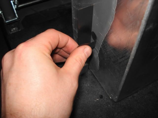
Eventually a plan was hatched: using shims and JB weld (metal putty) would get the job done. The block was placed on the surface plate with the side surface down and the flat top surface towards me. This was checked with a square to see how much shim would be needed. I added shim from a cheap feeler gauge set under the side surface in the right spot until it was perpendicular with the top surface. The shim was then super-glued in place. Now for the fun part. Saran rap was stretched tight over the surface plate and secured with masking tape on the side surfaces, adjusting the tape to make sure it was pulled tight. Then non-petroleum based (important, oily stuff will crinkle it up) silicone spray was used liberally on the whole saran wrap surface. The JB weld was mixed up and applied to the side surface, more being put around the shim. Then the block was placed down on the plate, with the weight of the block pushing the JB weld down to the shim. It was left on the plate for a good 6-8 hours and then pulled off and any JB protruding off the sides trimmed off with an Xacto knife. Then it was allowed to fully cure for another 24 hours or so. It was then sanded down a bit with sandpaper double sided taped to the granite block until the shil was virtually exposed. Presto, perpendicular.
I used the same technique with the ends, checking with shim and gluing the right amount in the right places.
A mistake I made was using feeler gauges on the end instead of brass shim stock as I needed to drill through a place that was occupied with shim. It had to be "peeled off" and JB re-applied to the area, placed on the saran wrap surface plate dealie and then sanded down. The rest of the procedure was the same, though I had to do a little more fiddling with a file to get the end to where I wanted them (perpendicular to .0015" over 5")
There we go, main blocks ready.
-
01-02-2010, 06:41 AM #5
Registered
- Join Date
- Mar 2008
- Posts
- 201
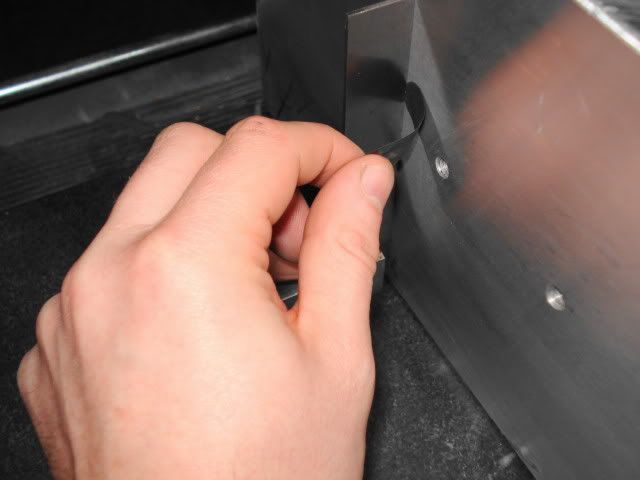
I wanted to work on the column (Z axis) next. First up, the holes for the rails. This was done with surface plate scribing to get two hole locations for the first rail (As far apart as possible with the 10" height gauge). These were optically center punched, drilled on the drill press and tapped.
http://www.leevalley.com/wood/page.a...=1,42936,50298
With the rail positioned parallel and straight to the block with adjustable parallels the two rail screws were tightened. Then the remaining holes were transfer punched, drilled and tapped.
For the second rail the first two holes were done as before. Then the first rail was re-installed parallel to the block. Using regular and adjustable parallels the second rail was placed parallel to the first and the two screws were tightened. Then transfer punching, drilling and tapping as before. The holes for all three axis were done this way.
-
01-02-2010, 07:02 AM #6
Registered
- Join Date
- Mar 2008
- Posts
- 201
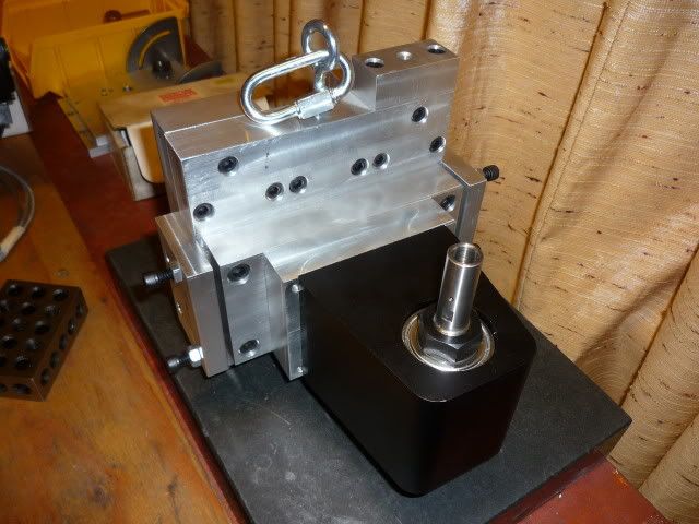
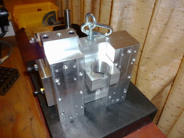
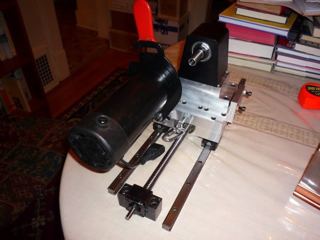
Next up, head assembly. First up was modifying the Sherline spindle for more solid mounting. Out of the box, the spindle had two 1/4-20 tapped holes and a key-way. This was not enough. I drilled and tapped four more 1/4-20 holes, one at each corner.
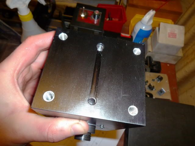
The plate that the spindle attached to had a .050" deep cutout that was less than half a thou wider than the spindle itself, providing a snug fit. So, the spindle would be held in place by the cutout and secured with triple the original amount of hardware. The spindle plate attached to another plate with a milled cutout barely wider than the plate and was secured with six 1/4-20 screws. A 1/2" dowel was pressed into this second plate.
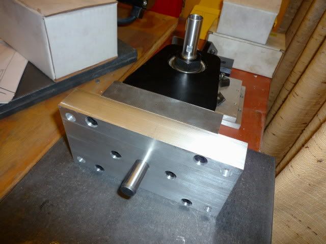
The rest of the head is shown assembled below. The spindle plate assembly is located and rotates about the dowel on the main plate and is secured with four 5/16-18 screws. Two tram plates on the side help to tram the head and provide additional support. The eye bolt and coupler are there for the counter weight.
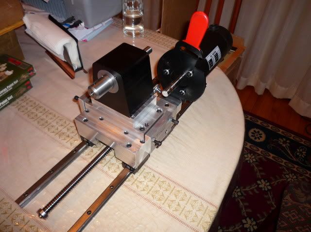
I did a mock up after with the motor. The motor is from a Penn State industries DC variable speed motor kit originally for the lathes they sell. It is a 1/2HP, 1700 max RPM motor. The control is a turned knob, 20-100% of motor RPM with load compensation. It's on sale right now for $100.
http://www.pennstateind.com/store/TCLVSKIT.html
-
01-03-2010, 07:49 PM #7
Member
- Join Date
- Feb 2008
- Posts
- 521
Not wanting to rain on anyones parade but I can't find any triple stack Nema 23's that'll manage 600oz! Generally all top out at about 380-390oz? So are these Nema 34's in which case they are underperforming or true Nema 23's which are possibly being asked to do more than they are able although with linear rails this is difficult to imagine. Without knowing what is in the CandCNC Blade Runner box it is difficult to diagnose but the manual refers to an internal fan - is this working? Have the G251's been installed correctly with a decent heatsink? Doesn't seem right having to suppliment cooling for a purpose made box?Electronics are by CandCNC. Initial performance looks to be very good. Fast and plenty of power. I got the Blade runner complete system with upgraded steppers and power supply (600oz-in and 48V). Yes, 600-oz in NEMA 23's running off a Gecko 251 based system.
-
01-04-2010, 12:02 AM #8
Registered
- Join Date
- Mar 2008
- Posts
- 201
http://www.candcnc.com/
Click on "Complete Packages" at the top and then tabletop/benchtop. BladeRunner combo with upgraded motors. I have no way of testing or verifying this.
There is a small internal fan. The Controller is very cramped inside, I think that is part of the problem. Everything is crammed together.There is a plate at the bottom that is the heat-sink. I have now drilled a bunch more holes in the case and that has lowered the temp another 2* according to the sensor on the plate.
Sherline mode was switched on, this looks to have solved the problem.
-
01-04-2010, 07:32 AM #9
Registered
- Join Date
- Mar 2008
- Posts
- 201
Update: The Sherline mode fix has worked very well. No missed steps!
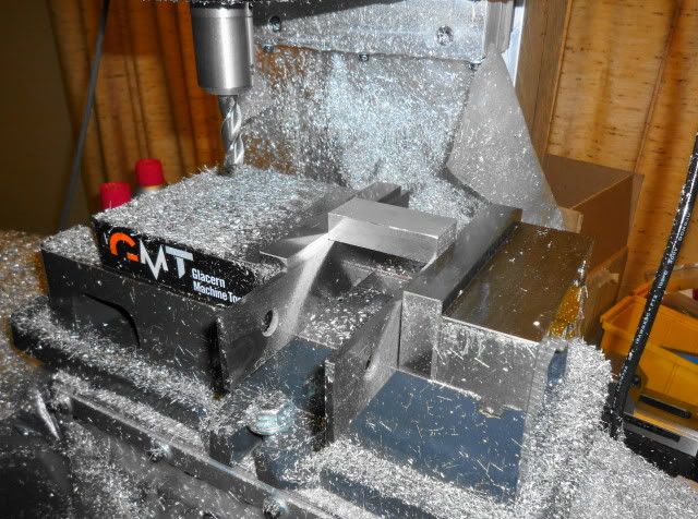
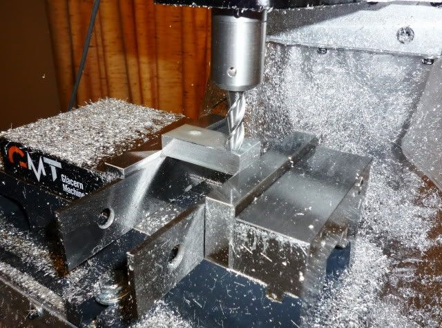
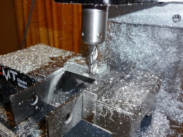
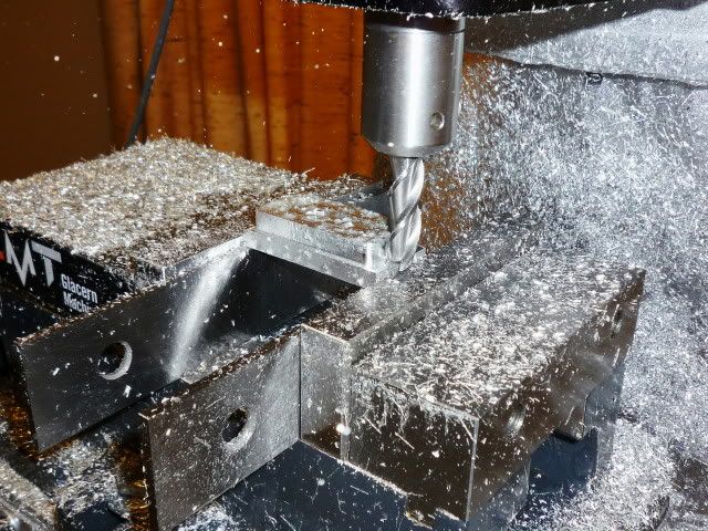
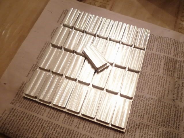
I've done stage one on a set of dominoes. The finished dimensions will be 1.75" by .875" by .25". A 2" by .5" billet of aluminum is cut into .95" lengths. The tool used is a 3/8", 3 flute, 1.125" cutting length Sowa aluminum cutting (high helix) carbide endmill with a .005" rad at the corners. Run at 5,000 RPM for all ops. Stage one surfaces .006" off the top at 25 IPM, then roughs the profile at .043" DOC (.258" total, specified a max of .050") and 25 IPM. To end a finish pass of .005" full depth at 25 IPM. Total cycle time is 2:53. With the Sherline it was 12:30. I'm sure it could do 30IPM easy, there was no vibration at the spindle and these endmills like fast feeding so that would bring it down to 2:30 or so. Finish is a mirror.
-
01-04-2010, 04:32 PM #10
Gold Member
- Join Date
- May 2005
- Posts
- 2502
Lay those out as a strip of 4 on the vise and it'll go faster.
When you flip to face mill off the backing they'll drop out individually.
You can use work offsets in your program to make the coding easier.
Cheers,
BWTry G-Wizard Machinist's Calculator for free:
http://www.cnccookbook.com/CCGWizard.html
-
01-05-2010, 03:38 PM #11
Member
- Join Date
- Sep 2005
- Posts
- 1195
Hi Sergizmo,
What is that above mill, that round shape. Does it connect directly to sherline spindle. Do you think can mill any steel with this spindle. I am just want to know, I plan to buy this sherline also for my mill but I plan to mill steel. Thanks.
-
01-06-2010, 06:38 PM #12
Registered
- Join Date
- Mar 2008
- Posts
- 201
Sorry guys for not responding sooner. Originally Posted by asuratman

Hi asuratman,
Do you mean the motor? The motor is a 1/2 horsepower 1700 RPM DC motor with a simple load compensating speed control (knob) type system similar to those found on the Sherline. I have it belted 3:1 with L series timing belt pulleys for a max RPM of 5,000.
This may not be the best for steel. Unfortunately there are not many options besides the X2 spindle which is in my opinion crap. If you do go with the Sherline be sure to go with P/N 6501, 6502, 6503 or 6504. Those are the ones with the beefier case.
http://www.sherlineipd.com/spindles.htm
Do not get one of the all in one units with motor.
Serge
-
01-06-2010, 12:30 AM #13
Registered
- Join Date
- Dec 2009
- Posts
- 27
Nice machine you have built.
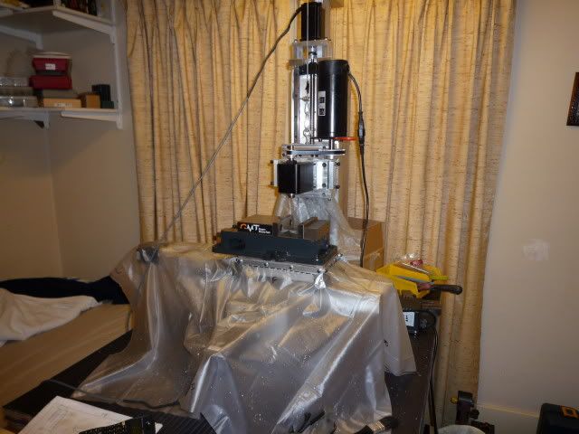
Is it really in your bedroom?
I hope to build something very close to that. With the set up you have how repeatable is it? Sorry its more than likely a stupid question but im new to DIY CNC's.
-
01-06-2010, 12:47 AM #14
Gold Member
- Join Date
- Aug 2006
- Posts
- 1602
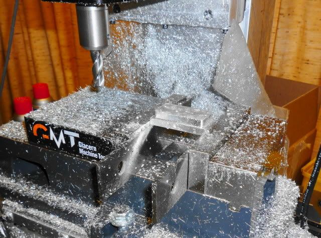
It does look like a nice machine, and he isn't the only one one here to be crazy enough to have a mill in an apartment, but with all those chips, I can't help thinking it's crying out for a full enclosure! Originally Posted by latheboy
-
01-06-2010, 06:50 PM #15
Registered
- Join Date
- Mar 2008
- Posts
- 201
Originally Posted by digits
Oh it is! When facing off the dominoes I was restricted to cutting in one direction to avoid blasting chips onto my bed. Hopefully in the next couple weeks...
-
01-06-2010, 06:48 PM #16
Registered
- Join Date
- Mar 2008
- Posts
- 201
Yes it's really in my bedroom. Originally Posted by latheboy
In terms of mechanical repeatability it's excellent, all 3 axis have only .0001" of backlash due to the ground screws (measured by jogging one way then the other with a tenths test indicator). Thank you ebay.
I'll have to get the steps per inch absolutely dialed in perfect in Mach3 to make an accurate assessment, but from what I can see so far holding +/- .001" will be no problem.
Serge
-
01-06-2010, 09:01 AM #17
Registered
- Join Date
- Oct 2007
- Posts
- 37
I dont even know where to start. Ill start with this awesome. How is the repeatability on it? What do you figure the total cost to be with vice?
-
01-06-2010, 06:53 PM #18
Registered
- Join Date
- Mar 2008
- Posts
- 201
Thanks! Originally Posted by vigilante212
As noted above backlash is excellent but I have to get steps per inch dialed in perfect to give a concrete number.
I'll give you a total cost in the next couple days.
Serge
-
01-10-2010, 10:36 AM #19
Gold Member
- Join Date
- Aug 2006
- Posts
- 1602
One thing I don't quite understand is why the steps per inch would need tuning - if you know the pitch of the screws and the ratios on any belt drive you might have on them, there's only one correct value, isn't there? Or are you talking about mapping the error along the entire length of the screw? Originally Posted by sergizmo
-
01-16-2010, 01:51 AM #20
Registered
- Join Date
- Mar 2008
- Posts
- 201
Yes, logically you would think it would be a simple conversion. I found the calculated values to be out a bit in actual machining and adjusted accordingly. And before anyone, asks, yes the axis were all aligned with an indicator. I can't really explain it but it is moving how much it should be with the tweaked values. Originally Posted by digits
I'm not doing any error mapping. They are Japanese ground screws, error is in the tenths over a foot. No biggie.

 Reply With Quote
Similar Threads
-
cnc vertical mill build log ( pics )
By katran in forum Vertical Mill, Lathe Project LogReplies: 122Last Post: 02-18-2024, 03:54 PM -
400W Mitsubishi HC-PQ43 Servos - choice for Vertical mill build
By fcp in forum Servo Motors / DrivesReplies: 0Last Post: 01-05-2013, 11:51 PM -
Looking to build a simple vertical mill
By Crudeau in forum Benchtop MachinesReplies: 7Last Post: 10-27-2012, 01:13 PM -
Custom CNC vertical Mill build T-Minus 24:00
By cncgabe in forum Vertical Mill, Lathe Project LogReplies: 37Last Post: 03-31-2012, 02:18 AM -
1st CNC Build - Aluminum & PCB Mill
By viroy in forum Open Source CNC Machine DesignsReplies: 2Last Post: 02-24-2009, 04:39 PM
