


Ok I’m kicking off plans to build my second router. My first was a jgro, witch is still in operation but I long for something that’s just a little more, you know a little bigger a little faster… (I have been told it’s a sickness) Will it ever end?
I’m not ready to give up the space it would take for a 4’x 4’ machine so I plan to build one that will handle 2’x 4’ maybe a bit more. I know there are some good designs out there like the Joe 2006 and the Lion Claw LC50 and I will be pulling together ideas from all over the Zone as well as the Net in general with a few of my own ideas mixed in (whether original or not) I am open to suggestions, not trying to reinvent the wheel here just build a sturdy machine.
The Pic below is the project I am currently working on.
RobWms
Results 1 to 20 of 172
-
01-21-2010, 07:10 PM #1
 Registered
- Join Date
- Aug 2005
- Posts
- 437
 Chronicle of a Geek! (Part 2 A new dawn)
Deeds not words...
Chronicle of a Geek! (Part 2 A new dawn)
Deeds not words...
VoltsAndBolts runs RC for the builder. http://www.voltsandboltsonline.com/ My Forum
-
01-22-2010, 02:43 AM #2
Registered
- Join Date
- Jan 2009
- Posts
- 72
This will be a thread not to miss.
Looking forward to the upcoming posts:banana:
-
01-22-2010, 11:01 AM #3
Registered
- Join Date
- Aug 2005
- Posts
- 437
Thanks denz, Me too!
I will try to keep you updated, but sometimes the rest of my life gets in the way of my fun. I will try to post a few more views of what I have come up with so far.
RobWmsDeeds not words...
VoltsAndBolts runs RC for the builder. http://www.voltsandboltsonline.com/ My Forum
-
01-22-2010, 01:46 PM #4
Registered
- Join Date
- Aug 2005
- Posts
- 437
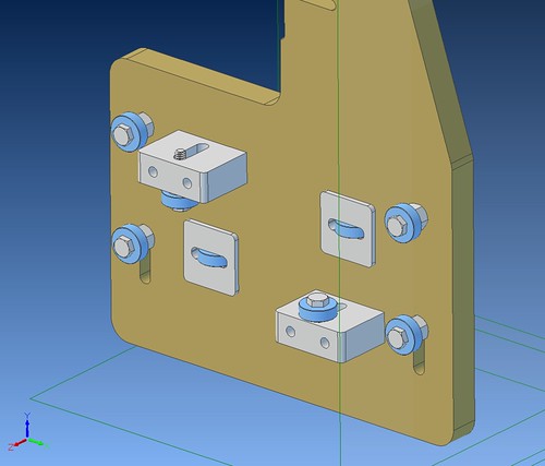
Ok, a look at how I may do the steppers on the main axis. I am also thinking of a single motor in the middle with a belt drive out to the lead screws.
[IMG]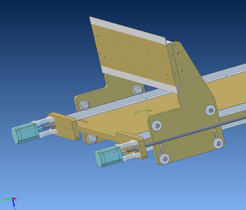 [/IMG]
Deeds not words...
[/IMG]
Deeds not words...
VoltsAndBolts runs RC for the builder. http://www.voltsandboltsonline.com/ My Forum
-
01-22-2010, 05:00 PM #5
Registered
- Join Date
- Dec 2009
- Posts
- 10
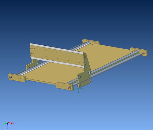
Is the base plate going to stay a single plate or are you going to add a torsion box ?
I love those V groove bearings but they are just so BLEEP expensive :P
-
01-22-2010, 06:00 PM #6
Registered
- Join Date
- Aug 2005
- Posts
- 437
This is just a concept at this point. Yes a T-Box or some other support (metal frame) will be needed to prevent sagging of the MDF. The best price I’ve seen on the V-bearings is about $10 each. I am working on a cheaper solution though…
Rob Wms.Deeds not words...
VoltsAndBolts runs RC for the builder. http://www.voltsandboltsonline.com/ My Forum
-
01-23-2010, 12:00 AM #7
Registered
- Join Date
- Dec 2009
- Posts
- 10
Now I'm curious

I've just ordered 40 bearings to create the linear guides like from buildyourcnc.com
-
01-23-2010, 06:35 PM #8
Registered
- Join Date
- Aug 2005
- Posts
- 437
40 of them $$$ Ouch!
 That site is very inspirational!
I am trying to keep my design easy to build with all of the more complex shapes sized to fit on my JGRO. I love the V-bearings but need a source in the $4 or less per unit to be practical. I bought 100 skate bearings when I built the JGRO so I’ll probably find a way to use them.Deeds not words...
VoltsAndBolts runs RC for the builder. http://www.voltsandboltsonline.com/ My Forum
-
01-23-2010, 07:06 PM #9
Registered
- Join Date
- Dec 2009
- Posts
- 10
40 V bearings :banana:? I WISH
they are just to expensive. I meant 40 * 608ZZ simple bearings.
This is the style I am going to build :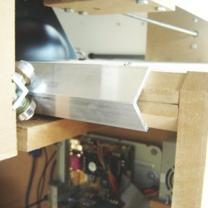
I've seen one alternative to V bearings by just bolting together 2 normal bearings. But the axial loads would be high and the created slot very shallow.
Therefore I've opted for the methode in the picture. More work while building but cheaper in materials. Also the possible issues finding a replacement bearing when a V bearing fails made me go for the simple bearings.
-
01-23-2010, 07:16 PM #10
Registered
- Join Date
- Aug 2005
- Posts
- 437
Hey they work and there fiscally responsible too!
Deeds not words...
VoltsAndBolts runs RC for the builder. http://www.voltsandboltsonline.com/ My Forum
-
01-23-2010, 07:27 PM #11
Registered
- Join Date
- Aug 2005
- Posts
- 437
Hey they work and there fiscally responsible too!
Deeds not words...
VoltsAndBolts runs RC for the builder. http://www.voltsandboltsonline.com/ My Forum
-
01-28-2010, 01:26 PM #12
Registered
- Join Date
- Aug 2005
- Posts
- 437
I see a lot of guys are using Vcarve Pro, it looks like an awesome package and I would love to have it… maybe some day. I have been using ACE converter (It makes notoriously inefficient code) and some hand coding but finally sprang for something that will let me design and cut without having to deal with the coding too much. I picked up a copy of Cut2D It looks like it will fill my needs for now, and besides the Boss (Wife) said that’s all I could afford.

RobWmsDeeds not words...
VoltsAndBolts runs RC for the builder. http://www.voltsandboltsonline.com/ My Forum
-
02-01-2010, 06:59 PM #13
Registered
- Join Date
- Aug 2005
- Posts
- 437
-
02-02-2010, 02:59 AM #14
Registered


- Join Date
- Aug 2009
- Posts
- 392
That looks like it could work! You have both axes adjustable, so I don't see any reason why it wouldn't. 8 standard bearings will cost a lot less than 4 v-groove bearings
-
02-02-2010, 04:40 AM #15
Registered
- Join Date
- Jan 2008
- Posts
- 853
tensioners?
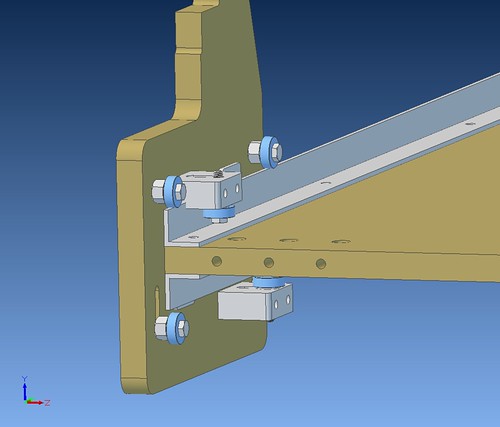
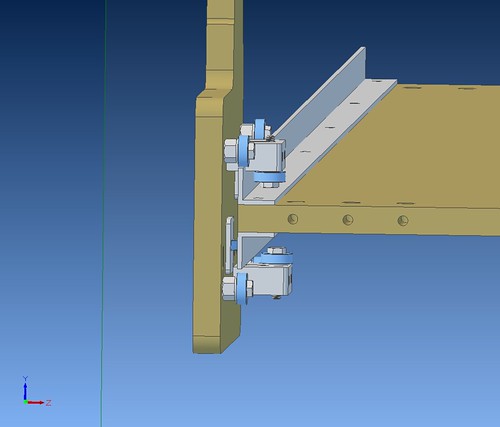
Adding tensioners into the sliding elements would make adjustments more secure (much like Ahren's metal carriages). For the vertical slots in the MDF, you could mount a cross dowel in the slot, then thread a rod up from the bottom of the gantry side, through the cross dowel, then on to press the 5/16" axle upwards against the rail material (CR steel plate?). Some kind of inside radius half-round to press against the axle would be best. For the vertical axes it is tougher to arrange and access the tightener, but it could probably be done.
It would be much easier to adjust the vertical axes rollers if the fixed roller was on the inside of the gantry, and the tension was applied to the roller riding on the outside face. Then the same cross-dowel trick would work.
Cheers!
-
02-02-2010, 05:40 PM #16
Registered
- Join Date
- Aug 2005
- Posts
- 437
Paul
These models are just conceptual at this point, There are a lot of things I have thought of and haven’t taken the time to detail in the model, and a lot of things I haven’t though of. I agree on the use of a tensioning device. I was going to just drill through the end of the slot and slip a nut into the slot. Cheap and easy.
Yes, it should run ok on a piece of CRS plate or on two opposing pieces of angle as shown in my first post.
Thanks for the comments, I am open to suggestions.
RobWmsDeeds not words...
VoltsAndBolts runs RC for the builder. http://www.voltsandboltsonline.com/ My Forum
-
02-02-2010, 06:49 PM #17
Registered
- Join Date
- Dec 2009
- Posts
- 10
Wouldn't the design allow the gantry bottom to be pushed away from the base ? I think you would need to connect the sides of the gantry below the base to keep the sides tight to the base.
I'm going for this design :
This locks the gantry side and doesn't allow it to move up,down left or right.. just back and forward. This also prevents the gantry from skewing.
-
02-02-2010, 08:28 PM #18
Registered
- Join Date
- Aug 2005
- Posts
- 437
-
02-03-2010, 12:10 PM #19
Registered
- Join Date
- Dec 2009
- Posts
- 10
Ahh.. okay. I misunderstood. Looks like it is going to work
-
02-04-2010, 12:51 AM #20
Registered
- Join Date
- Nov 2009
- Posts
- 36
What are you using for the rails?

 Reply With Quote
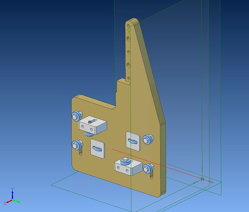
Similar Threads
-
cant get rid of solidcam from a part created internally within the solidworks part
By Nava in forum SolidCAM for SolidWorks and SolidCAM for InventorReplies: 3Last Post: 11-24-2013, 01:05 AM -
RFQ for part to mount on picatinny rail and sheetmetal part
By JAW in forum RFQ (Request for Quote)Replies: 5Last Post: 08-23-2012, 02:00 PM -
Chronicle of a Geek. (Jgro Build)
By voltsandbolts in forum Commercial CNC Wood RoutersReplies: 111Last Post: 06-18-2010, 01:45 AM -
Newb ? - CAD Part interference & mating part dims
By pabmartin in forum Mechanical Calculations/Engineering DesignReplies: 3Last Post: 11-06-2009, 07:18 AM -
"You might be a computer geek if..."
By HogDog in forum Community Club HouseReplies: 18Last Post: 01-10-2006, 02:58 PM
