


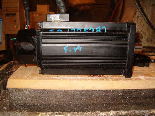
Well, this is getting expensive... I finally got my third drive. I've been keeping an eye on ebay for the last few weeks and a decent deal finally showed up. This one is another A-M-C drive, but is +/- 10V analog command. A bit smaller than the others, it is rated at 400Vdc, 40A max, 20A continuous.
This drive does it's own commutation, so I ended up ordering Renco RCML15 encoders, and since they are reasonably priced I ordered 3 to I won't have to do wake and shake on the other drives. Total for three Renco encoders, 2048PPR w/ index and hall tracks was $215 shipped. Not to bad IMO, but I will have to align them with the field. It looks like it is not going to be very difficult thanks to excellent instructions on the Renco web site.
I did the CAD drawings for the BOB's in eagle, and the mill is cutting the last one right now. They are nothing fancy, they just break out two 50 pin IDC headers and one 26 pin IDC header to screw terminals. The Galil controller uses a 100 pin high density MDR connector for axis 1-4 and IDC headers for everything else. The 100 pin MDR connector is a B*tch! I ruined one already trying to make the cable, so I ordered two more and and going to try my hand at making a fixture to align and hold everything. 3M gets over $3K for their "hand" version of the crimper, so I figure I can go through a few $15 connectors as a learning experience and still be ahead of the game.
Hopefully I'll have my BOB's and cables made by the end of the day and will take some pictures.
Results 21 to 40 of 46
-
05-17-2010, 03:50 AM #21
 Registered
- Join Date
- Sep 2007
- Posts
- 119
-
05-17-2010, 03:53 AM #22
Registered
- Join Date
- Sep 2007
- Posts
- 119
Well, it took a bit longer than expected, but I finished up today. The new fixture helped a ton for the MDR connector. I actually just copied the lower platen from 3M's pictures of the crimper, machined something similar out of scrap 1" ABS and used 3M double sided super tape to keep the wires aligned as I put them in place. Crimping it turned out to be an interesting exercise. I kind of mangled the shell, but it still works. If I end up doing any more of these, I am going to build a little press for it as well. Can't crimp them in a standard IDC press because the pair of ribbons come out the center of the connector.
Anyhow, it worked. Both BOB's are done, bellow is a picture of the cable and the BOB. I know the layout of the BOB isn't stellar, but it allowed me to keep it single sided. If it is to crowded in the inside parallel rows of screw terminals, I'll just separate the boards into individual 50-50-26 pin boards.


-
05-17-2010, 03:54 AM #23
Registered
- Join Date
- Sep 2007
- Posts
- 119
I made a little more progress today. I got my differential encoder break out board designed and cut one on the mill and soldered it up. The Renco encoders I bought are single ended, so this little board (1.5"x1.6") has a AM26C31 Quad differential line driver and takes the encoders wire connections via screw terminal blocks, passes through the halls and converts the single ended encoder data to differential. All of this is brought out to a DB15 connector. A lot of the stuff I'll be using had DB15 for interconnects, so to consolidate the number for connectors I have to go with, I figured I'd use it here too. This board will fit in the back of the motor/encoder housing and the DB connector will face down, under the cover, it should be fairly safe.
Here are the pics, I still have to test it to make sure the line driver works as intended.


-
05-17-2010, 03:56 AM #24
Registered
- Join Date
- Sep 2007
- Posts
- 119
Encoders are installed and halls are aligned, no pics, I was exhausted by the time I finished yesterday. Suffice it to say, there is nothing to be scared of, it is a very simple process w/ a dual channel scope. I am working on finishing up my encoder covers right now, then I am going to mill the Nema 42-->servo adapters I designed this morning over breakfast
 Hopefully I will get some pics today.
The encoder covers are all done, and that is as good as it gets for today. Paint is taking far to long to dry, and I'm going to call it a night. Here are a few pictures of the finished product.
This particular cover cracked in two when I started to modify it. I had to tig it back together, you can see in the bottom of the inside where I milled the weld bead out of the inside of the cover. It is solid and turned out pretty good. The other two covers came off w/o a hitch.
And since I forgot to mention it, I did test the differential line driver yesterday and it works as advertised!


-
05-17-2010, 03:58 AM #25
Registered
- Join Date
- Sep 2007
- Posts
- 119
I got a bit more done today. I repainted the encoder covers yesterday, evidently, the rattle can I had was past it's shelf life, it didn't dry completely in 3 days time, so I stripped it and started over.
So, anyways, I needed to come up with some sort of liquid tight enclosure for the main motor power wiring, since these servos came off a robot, they terminated the harness in a 18" pig tail w/ quick connects on the end. At the motor itself the wiring went through a grommet and a little aluminum cover w/ gasket to the motor, probably splash safe, but not sealed enough for the mill.
I looked through the water tight nema enclosure offerings at McMasterCarr, but they are pricey-- starting around $60 for a small one. I decided to go to my local big box home depot and see what I could rig up. I ended up with 3 die cast aluminum single gang boxes rated for wet location.
You can see all the gory details of what I did to them bellow, but the short version is, I milled the threaded conduit boss flush on the inside back of the box, and I milled the back outside of the box flat. I milled .125" off the top of little aluminum covers that originally sealed the motor. I basically turned them into little riser blocks. I made gaskets to seal between the aluminum box and the riser and assembled it all back together and painted them to match the motors. I used a water tight compression/grommet connector for wire entry. I am probably going to have to find the same thing in right angle style, because it looks like they may interfere w/ the encoder connector. The other hole in the box just got a threaded plug that was included in the package. The boxes were only $4.50 each, so it seems it will be a good inexpensive solution. The only thing I am not happy with is the covers. They are blank single gang SS covers w/ a foam gasket. I will probably machine some nice covers w/ real gaskets in the near future.
Anyhow, that is it for today, tomorrow I will hopefully get to the motor mounting brackets...


-
05-17-2010, 04:03 AM #26
Registered
- Join Date
- Sep 2007
- Posts
- 119
Well, I got the adapters all finished up today, all the holes are tapped and they mount up perfect.
Next on the agenda was lengthening the metric shaft and adapting it to something imperial. The stepper motor shafts are .625", and originally I was going to turn an adapter to go from the servo's 22mm shaft to .625-- well, w/o spacing the servos out even further, like another .75-1", the bore for the servo shaft would break through the smaller shaft. I could have pulled it off by shortening the servo shaft a bit, but I wasn't comfortable w/ that thin of a shoulder between the shaft sizes.
My Z axis timing pulley is in really rough shape, and the only reason I didn't buy a new one last time around is that these 11 tooth H series pulleys don't seem to be available anywhere. I am thinking I am going to order 22 tooth pulleys and bushings for all axis. This will mean the drive will be 1:1 now, The servos should have plenty of power to make up for the lack of reduction, and my overall speed will be even higher. Maybe to high. Give me your thoughts, I don't want to end up w/ an odd ball rev/inch ratio, that is why I am thinking matching the driven pulleys. I could get 14 tooth pulleys, but how will this effect my over all machine?
Anyhow, the shaft adapter is 1.375 OD on the servo end, 22mm bore, 1.1875 OD on the shaft end. I'm open to any suggestion on pulley configuration, I was planning on using pulleys from Mcmaster, between the bushes and the pulleys I am looking at about $60 per axis. Then I will also need new belts if I go as big as a 22 tooth pulley.


-
05-17-2010, 04:06 AM #27
Registered
- Join Date
- Sep 2007
- Posts
- 119
I made a bit more progress over the past few days. Not feeling so well, we had a cold snap here and I of course started to come down w/ a spring cold...
I got the shaft adapters all finished, keyways cut, and the bolt pattern adapters are all bolted up and good to go. Got the new 14T timing pulley installed on one of the servos, the others I made the shaft adapters step down to 1" shaft so I could buy replacement taper lock bushings for the pulleys that are there. All that went well, then today I pulled the cover off the Y axis motor and found that it's timing pulley is fixed bore. I think I am just going to order another 14T pulley and use those for X and Y and the Z will get one of the left over 11T pulleys. I really can't believe this thing had three different types of timing pulleys-- the Z is a cast aluminum job that is garbage and nearly destroyed, the X has a taper lock bush and is steel or cast iron, the y is fixed bore and steel or cast iron. Must be someone had their fingers in the pie before I got it...


Well, that is where I am at right now. I got the second replacement timing pulley in the mail the other day and hopefully when I am off work this week I will get a little more progress made.
Thanks,
Jason
-
06-04-2010, 07:55 PM #28
Registered
- Join Date
- Sep 2007
- Posts
- 119
Finally, I am off work for a while and am back at this. I am starting on the DC PS, that's the last thing on the list before setting up everything on the bench and beginning the rough tuning...
What I did today was complete my rack for the DC filter caps and made buss bars, ect... This would have been done a week ago, but last week the motor on my lathe died a sudden death. I had to make the 3/8" coupling nuts because I needed some custom sizes to make this work. I was drilling the hex stock and the lathe went boom. A few hundred bucks later, and it is back up and running well enough for me to finish the nuts and get this thing together.
Material for the rack is .125" and .25" acrylic. I chose acrylic because, #1 I had enough scraps to do this piece and not have to cut into any virgin stock, #2 because acrylic has a reasonable dielectric strength and will be a good insulator for the ~360Vdc buss, and #3, since it is clear, I can easily do a visual inspection to be sure the caps aren't beginning to bulge or leak.
The caps are 400Vdc, 450Vdc surge, 4300 uF each. The buss bars are cut from .75x.1875 copper stock. This should be more than enough capacitance to filter supply ripple.
I think I am going to run the DC supply from single phase 220 instead of the 3 phase 220, just so I don't have to start the rotary converter when I am using the 110V high speed spindle to do engraving. It means running another 220 line in the shop, but it should save money in the long run not having to have the converter running whenever the mill is.
Here are the pictures:


Later,
Jason
-
06-04-2010, 08:10 PM #29
Community Moderator
- Join Date
- Dec 2003
- Posts
- 24221
Not a big deal, but the up side is that Much lower capacitance is required when using 3 phase. Originally Posted by jacampb2

Higher frequency ripple and ~30% before filtering instead of 100% amplitude.
Al.CNC, Mechatronics Integration and Custom Machine Design
“Logic will get you from A to B. Imagination will take you everywhere.”
Albert E.
-
06-07-2010, 08:49 PM #30
Registered
- Join Date
- Sep 2007
- Posts
- 119
Here is a schematic of the plan for the PS. A guy on the HSM board suggested I use AC motor run caps instead of power resistors for in rush current limiting, so I designed this way. I *think* this should work, give me your thoughts. I still don't have any idea how to size the pre-charge caps. I am not finding much info online, hopefully someone w/ experience will be able to help...
Here is how it should work, the 110V control voltage is fed through the NC aux contacts on the main contactor and causes the pre-charge contactor to pull in supplying 220V through the in-rush limiting capacitors. The relay coil across the DC buss has a series resistance of 220K which should cause it to close at ~220Vdc. This relay feeds the main contactor control which then closes, the aux. contact go open and the pre-charge contactor drops out. If the voltage drops bellow ~180 Vdc on the buss, the cycle repeats...
Here is the schematic:

Thanks,
Jason
-
06-07-2010, 09:04 PM #31
Community Moderator
- Join Date
- Dec 2003
- Posts
- 24221
As with a resistive component, it will depend on the current at any given time which is going to initially be very high and decrease rapidly as the caps charge until the point the rectifiers are going to be reverse biased which should be under a second I would think?
I would try minimum 10µf.
You can calculate the capacitive reactance in ohms of the caps at 120hz by simple formulae.
http://www.st-andrews.ac.uk/~www_pa/...lex/react.html
BTW, if still using the 3 phase bridge, you may as well tie the spare bridge input to one of the AC inputs this way you at least parallel two pairs up and make use of it.
Al.CNC, Mechatronics Integration and Custom Machine Design
“Logic will get you from A to B. Imagination will take you everywhere.”
Albert E.
-
06-10-2010, 09:02 PM #32
Registered
- Join Date
- Sep 2007
- Posts
- 119
Well, I made some progress today. I got a long ways toward building a supply on my bench for testing the supply design, and if that goes well, then testing the servo amps and beginning tuning. All I have left is wiring up the 110V control side of the system, probably 30 more minutes of wiring. My wife asked me to come in for the afternoon, so I am on hold 'till tomorrow...
Here is a picture of the mess/PS on my bench, also a pic of the BOB w/ it's labels on now, and my attempt at DIY shielding on the IDC cables. Seems like it should work-- better than nothing anyhow.


Later,
Jason
-
06-12-2010, 12:41 AM #33
Registered
- Join Date
- Sep 2007
- Posts
- 119
I gave the supply a test run on the bench today. The good news is, the AC caps work great to limit inrush, the buss takes approximately 10 seconds to come up in voltage. The bad news is, the relay that is supposed to sense the buss voltage did not pull in when it should have. In fact it never pulled in at all, and the buss made it up to 300Vdc through the caps.
So, it is back to the drawing board to find something reliable to engage the mains contactor, I am first going to try dropping the coil resistance of that relay and experimenting a bit, but if that doesn't provide reliable results then I'll have to start working on some other method.
Thought you all might want to know I lived through the initial testing...
Thanks!
Jason
-
06-12-2010, 12:52 AM #34
Community Moderator
- Join Date
- Dec 2003
- Posts
- 24221
The current through a 220k resistor at 300v disregarding the coil drop is barely 2ma, what is you relay rated for?
I am not surprised it did not pick up. The dissipation of the resistor would be around .4w
Al.CNC, Mechatronics Integration and Custom Machine Design
“Logic will get you from A to B. Imagination will take you everywhere.”
Albert E.
-
06-12-2010, 01:21 AM #35
Registered
- Join Date
- Sep 2007
- Posts
- 119
I think I see what I did wrong! Coil current is ~27ma, when I read through the data sheet, I used the figures for a different relay, same model, different coil. I'll go back through it and see if I can come up with some better numbers. Originally Posted by Al_The_Man
Thanks,
Jason
-
06-16-2010, 12:42 AM #36
Registered
- Join Date
- Sep 2007
- Posts
- 119
Update for today: I got the supply working. The voltage sensing relay resistance still needs some fine tuning, it pulled in at 120Vdc w/ a 10K coil resistance. This is about 120V lower than I wanted it to, but I'll get it fine tuned. At 120Vdc when it engages the main contactor, it has limited enough that the supply doesn't blow the breaker, but it still does dim all the lights in the shop. I think if I get the main to pull in around 200-240Vdc, then it will be about perfect.
I'll work some more on it tomorrow and let you all know what I find.
Thanks,
Jason
-
06-16-2010, 09:06 PM #37
Registered
- Join Date
- Sep 2007
- Posts
- 119
Well, I have it up and working how I want it. The mains contactor energizes at ~215Vdc. The magic number for the relay coil resistance ended up being ~21.5K.
I needed a power resistor for the additional relay coil resistance. If it had worked out at 10K, the resistor would have needed to dissipate ~9 watts. I didn't want to buy a power resistor and then find it was wrong, so I decided to make a resistor array that would be capable of handling the power, and would be fairly easily modifiable if I needed to change values. I used a little radio shack piece of perf board and originally I started with 47 470K 1/4W resistors. This gave me 10K w/ an approximate power rating of 12W, the layout would not survive that power level for long, but it was good enough for testing. When 10K didn't work out as desired, I dropped a 10K 1/4W resistor in series, I knew it wouldn't last long trying to dissipate 2.5 watts, but I needed an idea where I needed to go w/ the power resistor. At 20K the resistor pulled in at 200Vdc, so I removed the 10K 1/4W resistor, and started pulling 470K resistors out of the array. I left 22 470K resistors in parallel, this gave me right around 21.5K with a power handling of 5.5W or so. With the resistance being higher, the power handling was still in range. I tried it out, and it worked great, so now I have my number for the power resistor I need to order.
Here is a picture of the DIY power resistor, and bellow that is a link to a short video of the PS coming up and running.

Servo_supply powering up
Thanks,
Jason
-
06-22-2010, 04:38 PM #38
Registered
- Join Date
- Apr 2005
- Posts
- 40
I just looked at your schematic. Please tell me the 240 vac input is comming from an isolation transformer and not the 240 vac mains.
cnc4me
-
06-22-2010, 05:50 PM #39
Community Moderator
- Join Date
- Dec 2003
- Posts
- 24221
What are your concerns over that? Originally Posted by cnc_4_me
Al.CNC, Mechatronics Integration and Custom Machine Design
“Logic will get you from A to B. Imagination will take you everywhere.”
Albert E.
-
06-22-2010, 11:24 PM #40
Registered
- Join Date
- Apr 2005
- Posts
- 40
“What are your concerns over that”
If there is no isolation transformer then both leads of the DC power supply will be 240vac above ground. This means if you ground the power supply like you should to chassis you will immediately blow at least one of your main fuses assuming you have a proper ground wire connected from chassis to ground in the 240vac feed from your house mains, and that is exactly what the safety ground wire is for. If you forgot this safety ground wire and you connect your DC bus to the chassis, then the chassis and the box it is in and machine it is mounted to will be at 240vac above ground level. Also if you connect this DC bus to a motor control, the logic and power grounds in the motor drive are common and you will feed back your rectified 240 v to all your electronics and immediately burn them up. In short, this is the worst case scenario for making a wiring mistake.
cnc4me

 Reply With Quote
Similar Threads
-
Lifting a B'port Series I R2E4 (BOSS-9)
By lloydsp in forum Bridgeport / Hardinge MillsReplies: 7Last Post: 01-07-2009, 12:53 AM -
B'port series 1 CNC Questions
By jacampb2 in forum Bridgeport / Hardinge MillsReplies: 1Last Post: 03-21-2008, 09:26 PM -
B'port tc22 / dx32 alarms
By edspert in forum Bridgeport / Hardinge MillsReplies: 3Last Post: 10-22-2006, 04:32 AM -
B'port board problem, please help
By fredhh47 in forum Bridgeport / Hardinge MillsReplies: 11Last Post: 02-14-2006, 04:41 AM -
Are thinking of going with Rutex drivers but what servos?
By kayakman in forum Servo DrivesReplies: 11Last Post: 11-15-2004, 11:48 PM
