


Hey guys, I in the process of starting a small custom snowboard company, and have had great success with my first CNC router. I was immediately bit by the CNC bug, and started formulating plans for two more CNC's, an edge bender to bend the steel edges, and a thickness planer converted to CNC for profiling the wood cores.
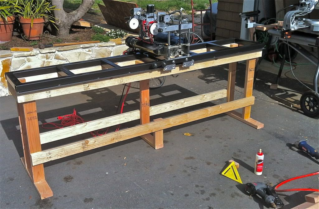
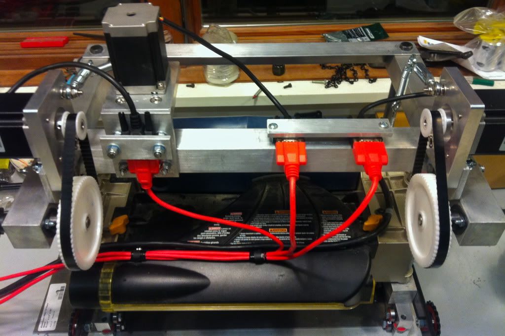
The design I came up for the planer uses the frame and motor of a 13" ryobi planer, a custom spiral cutter head, and an aluminum frame I fabricated to make the whole planer act as a gantry. The linear bearing system is the cnc router parts type with twin lead screws on the Z axis, and twin roller chain drives for the X axis. System uses (3) 380 oz/in steppers, Gecko G540, 14A 48v PS. Here are some pics of it under construction:
I have finished and calibrated it since the pics were taken, and it is working great with only minimal backlash on the X axis. I am currently finishing up the vacuum hold down table.
My main question is how to best go about programming it to profile my wood cores. The cores I use are approximately 170cm x 30cm x 1cm thick. The final snowboard core will be around 3mm thick at the nose and tail and gradually reach a thickness of 8mm in the middle. I have access to both mastercam X5 and HSMWorks. I've been able to get it to work programming it as if it were a 3 axis mill, machining a piece that's only .5mm in the y dimension, but I have not been happy with the toolpath. I would like to make numerous shallow passes along the entire x axis and have it cut in only the positive X direction. Any ideas how to best go about this? would treating it as a lathe be my best bet?
Thanks for the help guys, Ryan
Results 1 to 2 of 2
-
06-28-2012, 10:10 PM #1
 Registered
- Join Date
- Aug 2011
- Posts
- 0
2d programming for CNC thickness planer
-
06-30-2012, 06:57 PM #2
Member
- Join Date
- Feb 2009
- Posts
- 311
Cool project! Essentially what you have is a horizontal mill. You may be able to set up a horizontal mill directly in HSMWorks with the machine simulation, but right now I only have HSMXpress (it's free) so I can't really help with that specifically.
What I would do (with HSMXpress) is to pretend you machine is a regular 3-axis mill where the cutter is a huge face mill. This way the XYZ axes will be oriented the way you would normally expect a 3 axis mill to be, X left/right (length of board), Y forwards/backwards (width of board), Z up/down (thickness of board). You have no Y axis so that is basically just ignored. Once you have the job setup this way you would use the "trace" toolpath and select the top edge of the board that has the profile to cut. The trace toolpath basically just follows the the selected edge in XYZ. The direction to cut is determined by the arrow on the edge that you select. To reverse it just click the reverse button. In the toolpath parameters click the box for axial offset passes to enable multiple depth cuts and set the cut thickness and number of cuts. The trace toolpath cuts in one direction only by default but you can tell it to cut both directions of you like.
You may need to modify a post processor for your machine (to remove the Y axis commands for example) but that's fairly easy to do. What are you using for a motion controller? HSMWorks does have posts for Mach3 and EMC.
If you are modelling you boards in Solidworks already then HSMWorks/Xpress is definitely the way to go (for the planar and for the router too). If not, then there may be simpler ways to create the code for this machine. Since the code will be fairly simple you might be able to setup an Excel type spreadsheet to generate the code based on some input parameters, i.e. a list of thickness values along the length of the board. It would take some work to setup but shouldn't be too difficult.
C|
 Originally Posted by Rswilliams13


 Reply With Quote
Similar Threads
-
Anyone Own A Scheppach Planer/Thicknesser ?
By thkoutsidthebox in forum Metalworking- / Woodworking Tooling / Manual MachiningReplies: 8Last Post: 11-13-2011, 08:41 PM -
Helical Planer Head
By redlee in forum WoodWorking TopicsReplies: 8Last Post: 09-27-2010, 12:20 AM -
Pines Numbers 3&4 Benders Frame Thickness and Nose Thickness
By morribi in forum Bending, Forging, Extrusion...Replies: 6Last Post: 02-04-2010, 04:59 AM -
slope of a planer surface
By orizaba in forum BobCad-CamReplies: 3Last Post: 06-13-2008, 10:36 PM -
Converting Thickness Planer to CNC
By skibuilder in forum WoodWorking TopicsReplies: 15Last Post: 12-26-2007, 03:45 AM
