


Originally Posted by hoss2006

Yeah I gave that a try. Also used an external power supply to power the sensor switch with the black to input 1. Still nothing in Mach . Could I just use a wire plugged into input 1 a then one plugged gnd and jumper them to simulate a switch? Then I'd know if it's a problem with the a60 or on the mx3660 or my computer.
Andrew
Thread: Andrew's G07040 build
Results 41 to 60 of 241
-
01-29-2014, 09:17 PM #41
 Registered
- Join Date
- Sep 2012
- Posts
- 323
-
01-29-2014, 11:04 PM #42
Gold Member

- Join Date
- Nov 2009
- Posts
- 4415
Yes you can use a jumper between the pin and ground (do not use the external power supply). This will work well enough to detect on the diagnostics page. Originally Posted by Wiggles84
-
01-30-2014, 10:40 AM #43
Registered
- Join Date
- Sep 2012
- Posts
- 323
I gave the jumper test a try before leaving for work tonight and mach saw pin 10 light up when touching the wires. Glad that end of things seems to be in order :wee:
Out of all the possible issues, it coming down to the switches is the least expensive and best out come in my eyes.
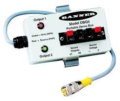
Now for those damn sensors! I brought all 3 with me to work tonight to put on our Banner Portable demo box (Model DBQ5) to see WTF is up with them. Well.... Each one acts differently when connected the same way? One will not power up at all, no out signal. One powers up and out puts no signal at all. the last one powers up and puts out a PNP signal, the puts out a NPN signal when switched.
So lets say that last is working properly, What is the right way to connect a 3 wire switch to the 2 wire connection of the MX3660 ? There is GND & Input1
If the MX3660 is putting out 12V then does that mean I would need a 12V external PSU IF I was to try to power these switches externally for it to see the signal?
Andrew
-
01-30-2014, 01:16 PM #44
Gold Member
- Join Date
- Nov 2009
- Posts
- 4415
If it is a mechanical switch then whichever pair give you a closed circuit. Upon breaking contact Mach is triggered. Actually either way will work but this way if any wire breaks the system shuts down. Wired the other way, the machine just keeps going even if the switch goes bad. If it is an electrical switch then all 3 wires will be needed.
"If the MX3660 is putting out 12v" Where are you measuring 12v? I suspect this circuit is 5v. If I understand this and your question correctly, you can use any voltage up to 24v. The higher voltage the more immune to noise the circuit will be. I believe the MX3660 or any controller is really just trying to detect the differential in voltages.
-
01-30-2014, 03:15 PM #45
Gold Member
- Join Date
- Feb 2006
- Posts
- 7063
Most prox sensors are open-collector output, and require a pull-up resistor on the output to get a reliable signal. Do you have a pull-up resistor on the output?
Also, you'll find prox sensors are less than ideal as home/limit switches, unless you can manage to completely protect them from chips. Even a rather small quantity of aluminum chips can cause them to trigger.
Regards,
Ray L.
-
01-30-2014, 03:23 PM #46
Registered
- Join Date
- Sep 2012
- Posts
- 323
They are the A60 from cnc4pc, 3 wire electrical switch. I guess They are a no go to power from the mx3660 given there is only 2 connections for each input (input# and GND). Originally Posted by Fastest1
I measured the 12V at the connections on the mx3660 (Input 1 and GND) It even says 12V sourcing in the manual, Page 19. I tried to power one of the switches with a 5V wall plug PSU yesterday but still could not get a signal in mach. Not sure which switch I was using so that maybe some of the issue there.
I think the next thing I'm going to try is putting the brown(+) and blue(-) on input 4's connectors and the black to input 1.
Andrew
-
01-30-2014, 04:16 PM #47
Registered
- Join Date
- Sep 2012
- Posts
- 323
So if I do make the jump to mechanical switches, do they need to be rated to with stand coolant? I plan to run flood.
Andrew
-
01-30-2014, 08:07 PM #48
- Join Date
- Feb 2013
- Posts
- 38
Thanks for sharing your experience with the switches. I was close to buying the same set up.
Take care
Kevin
-
01-30-2014, 09:38 PM #49
Registered
- Join Date
- Sep 2012
- Posts
- 323
No problem, thats why we post here. So others can learn from our mistakes! Originally Posted by Kevinj308

on that note..... I just bought a 10 pack of micro switches from the "E" site for under $9 shipped.
Andrew
-
01-31-2014, 12:35 AM #50
Gold Member
- Join Date
- Nov 2009
- Posts
- 4415
There is nothing wrong with your switches, likely just a wiring and or understanding issue.
Looking at the CNC4PC site, connect the blue wire to the ground, try the black and brown together to your pin (4)? The switch will not trigger anything unless the ground is used. Toggle between active low and see if it works. If you are getting 12v between ground and said pin, then that should power the switch, when it is triggered it will cut the path to ground or vice versa, I think (that is why I suggested toggling active low as a test). It is a 5-24v switch, so no damage should be done to anything if that is wrong. Let me preface it by saying. Test all of your switches on the diagnostics screen prior to initiating movement!
-
01-31-2014, 12:38 AM #51
Gold Member
- Join Date
- Nov 2009
- Posts
- 4415
Mechanical switches either need to be shielded very well or coolant proof. Or replaced often ;-)
-
01-31-2014, 09:53 AM #52
Registered
- Join Date
- Sep 2012
- Posts
- 323
I still think there is something wrong with the switches. none of them act the same on the tester. Originally Posted by Fastest1
Also tried the configuration you suggested and it no worky. I should have read through the mx3660 manual better before ordering the A60 switches. Lesson learnd!
Yeah I figured some covers were in order to protect them. Originally Posted by Fastest1
-
01-31-2014, 02:51 PM #53
Gold Member
- Join Date
- Nov 2009
- Posts
- 4415
Well it looks like your test equipment should let you know.
Dont feel bad on the reading of the MX3660. Seems like we are finding out a few contradictory things. Like do I need a separate power supply for my Bardac 1600i? ( I was told I didnt by 2 different vendors) Now I wonder. I have noticed there is a revised manual, that is not a good sign. The + is that my Dyna DM3000 for which I bought this controller has mechanical switches. For limits that is fine and the fact it is 12v would minimize the noise issue (at least better than 5v). However there are some optical switches within the tool changer I would like to reuse (if I can figure out what they do). Also my spindle encoder works on the same principle as your limits, so I wonder if that will work?
Generally when I have a problem like this (electrical/electronic) and nobody speaks up, I ask the super powers to intervene. At this point "Al the Man" usually chimes in with the voice of reason and experience. Typically a solution too. I suspect all hope is not lost on this 1, though I do suspect a wall wart or different/additional power supply will be needed.
BTW, The more I thought about the way I told you to hook up that switch, the more I suspected it wasnt going to work.
Are you using a resistor with that switch? Does Arturo recommend 1?
-
01-31-2014, 03:36 PM #54
Junior Member
- Join Date
- Nov 2008
- Posts
- 412
Hi Andrew,
On the first page you have posted pictures of your spindle motor/controller replacement. I was able to get the data from the picture of the treadmill motor label, and I presume this is the controller you went with > https://www.galco.com/buy/KB-Electro...MM-225D#bottom <. If so, did you try it to control the spindle by Mach3 or LinuxCNC successfully. Thanks.Forget about global warming...Visualize using your turn signal!
-
01-31-2014, 06:42 PM #55
Registered
- Join Date
- Sep 2012
- Posts
- 323
Originally Posted by lancut
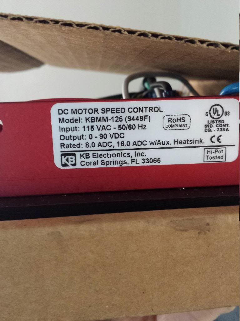
I got the same setup that Hoss is (maybe was?) using. so its a 1.75 hp continuous motor and a Kbmm-125 to control it with the 1.5 hp resister, (2) 25 amp fuses and the heatsink. He has all the links on his projects page. controller option #4
Link
As for mach control, I just started to really play with mach this last week. I may head to the basement once the kids are napping today to play with the spindle control settings. Still not sure if the MX3660 will supply the power or if I will need another PSU. Looking at the manual leads me to believe I will a 10V PSU as the kbmm-125 has no power output for this.
Andrew
-
01-31-2014, 06:56 PM #56
Registered
- Join Date
- Sep 2012
- Posts
- 323
I ready to just call it a wash on the A60. There may be a way to make them work. But with each one acting differently on the tester I'm not really confident in them. Originally Posted by Fastest1
I may jump to a DC 2 wire proximity switch at some point if I find a good price on them. But they seem to be an odd ball style as there are not may around on ebay.Each one acts differently when connected the same way? One will not power up at all and has no output signal. One powers up and out puts no signal at all. the last one powers up and puts out a PNP signal, the puts out a NPN signal when switched.
Andrew
-
01-31-2014, 08:16 PM #57
Gold Member
- Join Date
- Feb 2006
- Posts
- 7063
If they're behaving differently, it's almost certainly because you have(or at some point had) them connected incorrectly. Once you do that, no matter how briefly, they are almost certainly damaged, and will never work again. Also, it appears you never did put on pull-up resistors, without which they are unlikely to work at all.
Regards,
Ray L.
-
01-31-2014, 10:07 PM #58
Gold Member
- Join Date
- Nov 2009
- Posts
- 4415
Btw, I wrote Leadshine's technical support department about this and the 0-10v for the speed controller. Will post the response when I receive it.
A lazy man does it twice.
-
01-31-2014, 10:31 PM #59
Registered
- Join Date
- Sep 2012
- Posts
- 323
Figured That might have been part of the issues (Me not knowing wtf I'm doing!) So a $40 learning experience Originally Posted by SCzEngrgGroup

Thanks Originally Posted by Fastest1
-
01-31-2014, 10:57 PM #60
Registered
- Join Date
- Sep 2012
- Posts
- 323
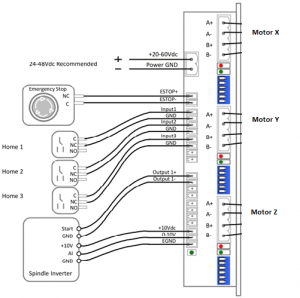
Been doing some digging on how to connect my KBMM-125 to the MX3660. Since the Gecko G540 is a similar device thats where I started looking for info. After reading a few threads it looks like the G540 can be used to replace the potentiometer to control the KBMM-125. Since the wording seems simular in the two manuals (G540 & MX3660) I figured I'd give it a try.
From the reading I gathered:- P1 is the +10VDC
- P2 is 0-10V
- P3 GND
Went to go give it a whirl... nothing happens. Put the Potentiometer back on the KBMM-125 to test things out.
I get:
- P3 ~ P2 0V at WOT (volts go up as I slow it down)
- P3 ~ P1 14V Constant
So Either I'm missing something in the equation of wiring or its my mach setup. I have PWM checked and set to 50. Set the pulley to 1000 rpm max at a 1 ratio (My Belt drive is a 1:1 ratio and I read somewhere that 1000 is a good place to start for rpm setting)
Theres got to be something in the potentiometer that makes it work, Or do I just have bad settings in Mach?
Some day I hope to have the answers and not be the one always asking for help:tired:
Andrew

 Reply With Quote


Similar Threads
-
Andrew's G0704 CNC Conversion
By andrew2085 in forum Benchtop MachinesReplies: 12Last Post: 01-21-2013, 06:04 PM -
Mint's Build Aluminum/Steel Build thread.
By FreshMint in forum Maintenance DIY DiscussionReplies: 0Last Post: 10-31-2011, 04:18 AM -
Newbie - To build or not to build Router/Plasma Table
By dfranks in forum Waterjet General TopicsReplies: 10Last Post: 04-08-2011, 05:16 AM
