


Can someone explain to me, how the retention knob is held by the rod when it retracts? I've been messing w/ a quick change adaptor for my spindle.. but haven't got my head around this part of the process.
Thnks guys
J
Thread: ATC Retention knob
Results 1 to 20 of 40
-
07-21-2008, 06:41 PM #1
 Moderator
- Join Date
- Sep 2005
- Posts
- 1660
ATC Retention knob
JerryFlyGuy
The more I know... the more I realize I don't
(Note: The opinions expressed in this post are my own and are not necessarily those of CNCzone and its management)
-
07-21-2008, 06:50 PM #2
Monkeywrench Technician
- Join Date
- Jan 2004
- Posts
- 3154
Jerry
I don't have time to get lengthy and I know you will understand anyway.
There are ball bearings in a retainer that close around the knob to "grip" it.
The ball bearings ride in a taper or step that is ground into the spindle that allow them to open when extending and close when retracting.www.integratedmechanical.ca
-
07-21-2008, 07:45 PM #3
Registered
- Join Date
- Jul 2007
- Posts
- 887
Here's a rendering of what DareBee mentions and how I did it my BT30 spindle.
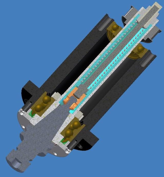
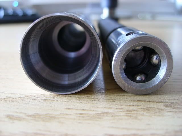
And here's a photo of the drawbar and the "drawbar tube", you can clearly see the chamfer that forces the balls in and "grips" the drawbar by its chamfer.
It seems though that most ATC spindles now use some kind of "springy" fingers in stead of balls. The principle is the same though.
/Henrik.
-
07-21-2008, 10:13 PM #4
Moderator
- Join Date
- Sep 2005
- Posts
- 1660
Ok, I figured it was something like this, but wasn't convinced that I could get the timing right to do an ATC.
When the pull rod is fully extended [tool released] is it pushing the knob and the tool holder out of the taper?
If yes, then when you actuate the rod to pull the tool in, are you pushing up on the tool to ensure that it will travel w/ the pull rod until the balls start to ride inwards on the taper and then it will seat into the taper[instead of the balls in the pull rod just slipping by the knob]?
If your doing this w/ an ATC sequence, does the Z axis traverse down the distance that the tool is held out of the taper, as the pull rod lifts?
I've never seen an ATC work in real life.. I understand the broad strokes of it, but the fine details are a bit fuzzy.. I've used a manual tool changer [threaded pull rod] and had to push the tool up into the taper until the threads started..
Thanks guys
JJerryFlyGuy
The more I know... the more I realize I don't
(Note: The opinions expressed in this post are my own and are not necessarily those of CNCzone and its management)
-
07-21-2008, 10:38 PM #5
Registered
- Join Date
- Jul 2007
- Posts
- 887
Hi Jerry,
Due to 'some' problems building my spindle it isn't running yet so I haven't worked out the exact details yet but yes, the drawbar pushes on the pullstud so that the toolholder will "let go" of the spindle taper. The next tool is then inserted, and the air cylinder pressing the drawbar down is deactivated. The bellevillewashers in the drawbar assembly then pushes the drawbar up making the balls grip the pullstud.
In my case I'll probably make it so the Z-axis come down so that the holder just barely or almost makes contact with the taper, perhaps there would need to be some "give" in the holders that the hold tools in the carousel or whatever but I think it's doable.
Problem now is I have to much runout, but that's another story...
-
07-21-2008, 10:46 PM #6
Community Moderator
- Join Date
- Mar 2003
- Posts
- 35538
On our router at work, the spindle drops pretty much all the way down so the taper is just about seated, before it grabs the tool. Our tools are held by pnumatic arms that position them under the spindle, and they have a little flex, but they are basically grabbed and released from the same position. These are HSD spindles. Hope this makes sense. Originally Posted by JerryFlyGuy
 Gerry
Gerry
UCCNC 2017 Screenset
http://www.thecncwoodworker.com/2017.html
Mach3 2010 Screenset
http://www.thecncwoodworker.com/2010.html
JointCAM - CNC Dovetails & Box Joints
http://www.g-forcecnc.com/jointcam.html
(Note: The opinions expressed in this post are my own and are not necessarily those of CNCzone and its management)
-
07-24-2008, 04:57 PM #7
Gold Member
- Join Date
- Aug 2006
- Posts
- 1602
Is there a good reason for this? The springy ones do look like they might require a smaller bore in the spindle, but I would have thought that the balls would wear less than the springs... Originally Posted by H.O
-
07-24-2008, 06:52 PM #8
Monkeywrench Technician
- Join Date
- Jan 2004
- Posts
- 3154
As it is sorta mentioned here - they tools are held in by spring pressure. It wouldn't be safe to use a cylinder in case of power failure or line rupture.
www.integratedmechanical.ca
-
07-24-2008, 08:49 PM #9
Gold Member
- Join Date
- Aug 2006
- Posts
- 1602
There are quite a few ATC's in action on YouTube - this is probably the simplest - simply a tool rach and a pull-stud spindle: Originally Posted by JerryFlyGuy
To me it looks like the spindle is fully down on the tool before the stud is drawn in.
Here though, you can see the tool get pulled up into the spindle and drop slightly out as it is released:
-
07-25-2008, 09:19 AM #10
Registered
- Join Date
- Jul 2007
- Posts
- 887
Honestly, I don't know - I seem to remember reading somewhere that the ball-type grippers failed more often - don't know how or why though.Is there a good reason for this? The springy ones do look like they might require a smaller bore in the spindle, but I would have thought that the balls would wear less than the springs...
That's not what I mean't with springy fingers.... I meant the part of the drawbar that actually grips the pullstud. The drawbar itself is springloaded in either case - balltype gripper or "springy fingertype" gripper.As it is sorta mentioned here - they tools are held in by spring pressure. It wouldn't be safe to use a cylinder in case of power failure or line rupture.
I've attached two pictures of the springy-finger-type gripper, sorry for the low resolution.
-
07-25-2008, 10:36 AM #11
Gold Member
- Join Date
- Aug 2006
- Posts
- 1602
Thanks HO - I found quite a lot more info on this rather slow website:
http://www.chumpower.com.tw/products...s_spindle.html
From the diagrams in the PDF, as far as I can see, the 'fingers' dont seem to be sprung, but rather hinged. It looks like the inside profile of the spindle bore is used to close the fingers against the stud.
I'm still leaning towards a ball-style gripper though as it looks a lot easier to make. How much of a stroke did you need to release/clamp a stud?
Cheers.
-
07-25-2008, 11:04 AM #12
Registered
- Join Date
- Jul 2007
- Posts
- 887
Hi Digits,
As designed, about 6mm. I used a 30° taper for the balls to ride on but that could probably have been 40-45° instead reducing the needed stroke a bit.
/Henrik.
-
07-25-2008, 04:38 PM #13
Registered
- Join Date
- Nov 2005
- Posts
- 256
I'm not advocating this idea because I don't how just how safe it is, but ...
http://www.harrisson.biz/video/PNQC.wmv
And the original post (that I saw) regarding it is at http://groups.yahoo.com/group/GrizHF.../message/13854
-
07-25-2008, 05:33 PM #14
Gold Member
- Join Date
- Aug 2006
- Posts
- 1602
Hmm, I don't think I'd like to mount a face mill using that system, and for me, an ATC needs to be able to handle all my commonly used tools.
There is already an R-8 pull-stud system commercially available, and I think I've seen the patent on line which has all the useful info...
http://www.mach-1tooling.com/
But I don't see the point of pullstuds on a non ATC-friendly flangless toolholder. I did toy with the idea of using just the tapered portion of R8 tool-holders and then putting a pullstud-gripper in the volume use by the straight shank portion of the R8-holder. It wouldn't be that stiff, but would have more contact area and less stickingout than the HighTech Rapid Changer I was using previously.
-
07-25-2008, 06:16 PM #15
Monkeywrench Technician
- Join Date
- Jan 2004
- Posts
- 3154
IMO the purpose of using fingers would be to allow for more surface contact on the ground taper inside the spindle. In theory a ball bearing has a very small point of contact and will wear grooves into the spindle much quicker.
www.integratedmechanical.ca
-
08-05-2008, 02:44 PM #16
Moderator
- Join Date
- Sep 2005
- Posts
- 1660
Guys, how much pressure is needed to retain a tool in? I've finally got my spindle design done, Abec 7 bearings thru-out [two on the btm, 1 on the top] as well as an air tool change. The pull rod is sprung via Belville washers. I've basically designed my own tool holder, but I'm going to see if it's adaptible to
something I can buy..
The spindle will be 'inline' direct drive from my current E/C spindle.
The atc spindle is ~ 5" long and 3.5" sqr so it's pretty compact..
Currently I've only got about 50lb's pull on the rod, this can be increased but it means I'd need a larger compressor to push the rod out, [or a single acting pressure intensifyer cylinder in between the two]....
Curious..
JJerryFlyGuy
The more I know... the more I realize I don't
(Note: The opinions expressed in this post are my own and are not necessarily those of CNCzone and its management)
-
08-05-2008, 02:54 PM #17
Registered
- Join Date
- Nov 2007
- Posts
- 24
Upward Pressure on Retention Knob
Seems like I heard a long time ago from one of the guys at an unnamed Spindle supplier of ours that the tension on the pull stud (retention knob) was a spring that pulled the toolholder up into the cone with upwards of 100 lbs force. He may even have said one hundred fifty pounds. (It has been about 11 years since I had that conversation with him.
Josh Glenn
www.camaster.com
www.cncexperts.com
Originally Posted by JerryFlyGuy
-
08-05-2008, 03:44 PM #18
Registered
- Join Date
- Jul 2007
- Posts
- 887
I think that it largly depends on the type and size of the tool/holder. I looked long and hard when designing my BT30 spindle and only found a few references. Here they specifiy the pullforce as 881lbs for a size 30 taper (3900N) and in my notes I've referenced a Prometrix catalog that specified 5500N for a size 30 taper.
Again, YMMV - a lot probably - but I used those numbers as a guideline and settled for 3000N. In the end it will probably be a bit less than that.
HTH
/Henrik.
-
08-05-2008, 05:23 PM #19
Moderator
- Join Date
- Sep 2005
- Posts
- 1660
Josh I guess I should have asked in the first post,.. How big was the largest tool that those holders were to hold in?
Thnks
JJerryFlyGuy
The more I know... the more I realize I don't
(Note: The opinions expressed in this post are my own and are not necessarily those of CNCzone and its management)
-
08-05-2008, 05:32 PM #20
Moderator
- Join Date
- Sep 2005
- Posts
- 1660
Also, I've not been able to find any dimensional info on retention knobs...
Anyone know where ta look? It appears that my machinist handbook doesn't have them.. but they did have a 30 taper tool holder dim's.. which were VERY close to what I'd originally modeled.. a simple thing to change mine to match..
JJerryFlyGuy
The more I know... the more I realize I don't
(Note: The opinions expressed in this post are my own and are not necessarily those of CNCzone and its management)

 Reply With Quote
Similar Threads
-
interact 4 pull stud/retention knob style?
By camarogod98 in forum Bridgeport / Hardinge MillsReplies: 1Last Post: 04-19-2017, 05:12 PM -
RETENTION KNOBS
By Jfrahm in forum CNC ToolingReplies: 3Last Post: 05-31-2008, 02:07 PM -
Retention Knob Cross Reference for 50 Taper?
By pdoherty in forum Haas MillsReplies: 2Last Post: 12-14-2006, 05:54 AM -
Retention Knob Help
By 1gonzo in forum DNC Problems and SolutionsReplies: 1Last Post: 03-17-2006, 05:44 PM -
Retention knob breakage
By Crash in forum Uncategorised MetalWorking MachinesReplies: 3Last Post: 11-03-2005, 09:12 PM
