


Maybe I'm wrong (not unusual), but think he may be asking the type of material used to make the gripper and drawbar?
Without going back through 100+ posts, I believe it was mentioned one time.
Thread: BT30 Spindle project
Results 121 to 140 of 174
-
12-13-2009, 05:45 PM #121
 Gold Member
- Join Date
- Mar 2004
- Posts
- 1806
Art
AKA Country Bubba (Older Than Dirt)
-
12-14-2009, 06:41 PM #122
Neuer Benutzer
- Join Date
- Mar 2007
- Posts
- 7
gripper and drawbar material ?
-
12-15-2009, 07:58 PM #123
Registered
- Join Date
- Jul 2007
- Posts
- 887
Hi,
Yes, the balls are ordinary 6mm ball-bearing balls. The gripper and the tube is machined from SS2511 steel (same as the spindle shaft), the gripper as well as the lower part of the tube (where the gripper is) is hardened. I don't know the exact material I used for the actual drawbar, some kind of steel.
/Henrik.
-
07-03-2010, 12:23 AM #124
Member
- Join Date
- Sep 2008
- Posts
- 229
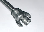
This post inspired me to make a finger-style gripper, mainly for fun. Originally Posted by digits

From Gibbs
It is a slightly unconventional design as it is for a 30INT spindle, and there is only 16.6mm of bore diameter to fit everything inside. (I guess I am lucky to have that much considering the drawbar isn't that big.
I was going to make it out of solid then slit it, but then I had a brainwave and cut 4 lengths of 10mm square steel which I held in a 4-jaw chuck in a square. I turned a spigot on one end and pressed on a little collar. That let me shuffle it out of the chuck and put a tailstock centre in and turn the OD.
[nomedia="http://www.youtube.com/watch?v=IJ9qVexXirk"]YouTube- IMG_0106.MOV[/nomedia]
With a special little boring bar and some CNC the inside was a lot easier than it would have been using manual machining, it would have been almost impossibly blind.
Being all machined in one setup, and as one piece, it should be a lot straighter than the 4-balls system. It is probably a lot weaker too, but balls wasn't an option with my spindle, balls big enough to hook the pull-stud wouldn't fit round the pull stud to let it out.
-
07-03-2010, 03:28 AM #125
Registered
- Join Date
- Aug 2007
- Posts
- 558
Hey, nice work Andy!!
-
07-03-2010, 08:26 AM #126
Gold Member
- Join Date
- Aug 2006
- Posts
- 1602
That looks fantastic! I had a go a while back at a ball type gripper - I had the luxury of a 19mm OD, but that still limited me to 6x 4mm balls and left me with a 20mm extraction stroke. I think your design looks far more sturdy. Originally Posted by andypugh


Do you need some kind of collar to force your gripper shut, or does the the top of the spindle taper do it for you?
I'm still looking for a UK source of Belleville washers - anyone got any suggestions?
-
07-03-2010, 09:57 AM #127
Member
- Join Date
- Sep 2008
- Posts
- 229
http://www.springmasters.com/disc-springs/index.html Originally Posted by digits
Pricing is about £10 per 100.
-
07-03-2010, 11:13 AM #128
Gold Member
- Join Date
- Aug 2006
- Posts
- 1602
Thanks Andy - that's very useful. Originally Posted by andypugh

What sort of drawbar force is typical for BT30 spindles? As I've got a 20mm extraction stroke, I'd quite like to stack a load of washers inside the spindle, which would limit me to 12.7mm OD washers, and a 6mm dia drawbar. Is that going to be too weak?
-
07-03-2010, 12:06 PM #129
Registered
- Join Date
- Jul 2007
- Posts
- 887
Hi guys,
That's a very nice looking gripper Andy. Personally I never got around to fixing the problem with my spindle, filed the project under failures and sold it on for another enthusiast to fix.... A propper gripper is probably the key to success.
As for retention force, I looked around quite a bit when designing my spindle. On this page Hardinge specifies 880lbs (~3900N) for their BT30 spindle and I have notes about 5500N being mentioned in some Prometrix literture but I've lost the reference. It was quite tricky to get both the needed force and travel in the space I had available, I used 114springs stacked three and three like this ((()))((())) but I "only" needed ~6mm travel IIRC, I can't imagine what it will take to get 20mm.
Remember that you need your 3000N or whatever when the gripper is "enganged" and the tool seated in the taper. That means that the springs will be partially compressed and you need a lot more force to compress them enough for the gripper to actually release the tool.
In my case it turned out that with the springs preloaded to s0.5 (50% compressed) I got ~3100N and to get the 6mm travel it took a force of 4500N, the full stroke from zero preload to 100% was 19mm in my case.
Keep up the good work guys and please keep posting!
/Henrik.
-
07-03-2010, 12:48 PM #130
Member
- Join Date
- Sep 2008
- Posts
- 229
As HO said, it is in the order of a few kN. You can work it out if you know the specified torque for a drawbar. T = kFd (T - torque, k = about 0.2, d is diameter). Originally Posted by digits
Looking at the springmasters table, the D125621 is 700N @ .08mm and 1.5kN @ .18. Put simply you get 700N per parallel set and 0.1mm per serial set.
(You can change that balance, more force, less preload)
4 springs in parallel is 4.08mm high @ 2.8kN You need 20/0.1 = 200 sets.
So, 800 springs, in fours, with a free length of about 1m.
I think your stroke is excessive. I was expecting mine to work with 4mm. It is probably worth setting up a spreadsheet to work through the permutations.
The other question is the stress in your central rod and outer tube, but even assuming mild steel and 200N/mm^2 your 6mm rod is good for 5.6kN (and I would hope you are using something better than mildest steel. 6mm silver-steel rod will be about 3x that strength.
-
07-05-2010, 06:42 PM #131
Gold Member
- Join Date
- Aug 2006
- Posts
- 1602
Thanks for that - yes, 20mm of stroke is a lot, but it seems to be what I need to get the balls far enough out of the gripper to allow the widest part of the pull-stud to move past. Originally Posted by andypugh
I suspect I'll have to have a 2-stage system for my spindle -with another ball-gripper on the other end of the spindle pulling the drawbar up:

This would have a much shorter release stroke, and could use much larger diameter belleville's to produce the ~5kN pull. Once the top-gripper had released, the 'core' of the drawbar would be free to move the rest of the extraction stroke.
It might be a lot easier to make a finger-gripper like yours though. Either way, I really want/need a CNC lathe
-
07-05-2010, 07:04 PM #132
Member
- Join Date
- Sep 2008
- Posts
- 229
Is the problem that you need to use the taper itself to make space for the balls? Originally Posted by digits
Is there any chance of stealing some more diameter for the washers? I have decided that 1mm wall thickness for my outer tube is plenty. Well, enough. Barely. If I use good enough material. I seem to recall you said you had 19mm diameter to play with? I think you will find that you get more travel from bigger washers for the same force.
D168209 is 800N @ 0.21mm and 1197@ 0.32mm
Double them: up each stack is 1.94mm @ 1650N and gives you 0.11mm travel.
So for 20mm you need a stack 180mm long, which sounds perfectly reasonable. (You can always have it stick out the top a bit)
-
07-05-2010, 11:14 PM #133
Gold Member
- Join Date
- Aug 2006
- Posts
- 1602
Yes - there is a parallel section about 50mm long, 19mm dia above the top of the taper, but as the balls are 4mm dia (which is too small really) and the widest part of the pull-stud is 11mm wide, the pull-stud has to move all the way down to the top of the taper before it can be released. Originally Posted by andypugh
Not really - the spindle really only has room for a 14mm dia drawbar - it was never designed to take a gripper.Is there any chance of stealing some more diameter for the washers?
What OD does your finger-gripper require to release the stud?
-
07-05-2010, 11:32 PM #134
Member
- Join Date
- Sep 2008
- Posts
- 229
Ah, sounds like I got very lucky with my 16.65mm drawbar bore. Originally Posted by digits
16.6mm :-)What OD does your finger-gripper require to release the stud?
I wonder if you could mount a spring-seat in the bore, and not have the external tube? Some sort of expanding collet or similar. It would only need enough hole in the middle to pass the pull-rod. I am thinking in terms of a tapered hex-socket plug into a split, threaded ring.
Also, check my working on the 12mm washers, I can't believe that the 14mm ones are different enough to explain the disparate results.
-
07-06-2010, 12:02 AM #135
Member
- Join Date
- Sep 2008
- Posts
- 229
Looking again, I have missed something of a trick. The thicker washers have less "dish" so less total travel. Originally Posted by andypugh
Looking at the 12.5 x 0.6mm ones you can get 1200N and 10mm travel in a 230mm stack. It's a fairly complex puzzle, possibly best solved graphically.
-
07-07-2010, 04:36 PM #136
Member
- Join Date
- Sep 2008
- Posts
- 229
I have produced a set of Excel plots of the displacement/preload for each of the DIN2093 disc spring sizes from 12.5 to 16.0mm dia (Producing others is not a huge amount of work)
The worksheet is here: http://www.bodgesoc.org/DIN2093DiscSprings.xls
The X-axis is how much deflection there is available on a notional 100mm stack and the Y axis is the load at that deflection.
So, for a 200mm stack of 12.5mm springs where you wanted 20mm travel you need to look at the 10mm point for the highest line. You can see that the choice would be between a 2-stack or a 3-stack of D1256206 springs, with the 2-stack probably being better (less extension sensitivity, lower release force) but with neither offering more than 700N force at that point.
To get 1500N with a 12.5mm washer stack you would need to use a 4-stack of the same D1256206 size, but then could only have 6mm travel per 100mm of stack.
(Interesting that the 1256206 (12.5 x 6.2 x 0.6) comes out as the answer every time)
-
07-12-2010, 11:47 PM #137
Gold Member
- Join Date
- Aug 2006
- Posts
- 1602
Thanks for those charts Andy - very useful! Basically my 20mm of ejection stroke can't be done without disengaging the spring stack first for any reasonable length of stack and drawbar tension.
-
07-12-2010, 11:51 PM #138
Gold Member
- Join Date
- Aug 2006
- Posts
- 1602
One thing I'd like to ask HO is just how critical it is to have the spindle taper hardened and ground?
Would it be possible to simply turn it on a lathe, and then treat the taper as a disposable item?
Toyoda have a removable spindle taper design, and I was thinking this might be quite doable as a DIY if you made the nose of the spindle into a huge flange - like a lathe spindle. You could also get zero runout by simply dialing the taper in before torquing it down...
http://www.toyodausa.com/spindlerepairsimplified.shtml
-
07-13-2010, 10:51 AM #139
Member
- Join Date
- Sep 2008
- Posts
- 229
-
07-13-2010, 09:58 PM #140
Gold Member
- Join Date
- Aug 2006
- Posts
- 1602
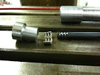
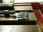
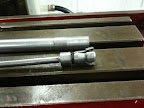
They look excellent Andy!
Is the 2nd photo a shot of the top of the drawbar? Are those 'keepers' - they look a lot like the widgets on top of engine-valves that keep the spring retainers on...

 Reply With Quote
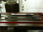
Similar Threads
-
BT30 Spindle cartridge for a smithy mill
By mlennon in forum Maintenance DIY DiscussionReplies: 0Last Post: 03-12-2013, 05:13 PM -
Looking for a BT30 Spindle
By xtwalt in forum Uncategorised MetalWorking MachinesReplies: 1Last Post: 11-20-2012, 10:10 PM -
BT30 Spindle
By dirtridn2010 in forum Tormach Personal CNC MillReplies: 0Last Post: 05-07-2012, 11:19 AM -
Reasonably priced BT30 ATC spindle.
By dwalsh62 in forum News AnnouncementsReplies: 0Last Post: 05-12-2011, 05:59 PM -
BT30 taper spindle for mold making
By grantmi1 in forum Hard / High Speed MachiningReplies: 5Last Post: 02-28-2006, 09:41 AM
