


I know I've already posted it in the Rhino subsection but have now decided it is more relevant in this section.
I am just starting to learn CAD and I need to trace a guitar body perimeter with the best curve continuity possible.
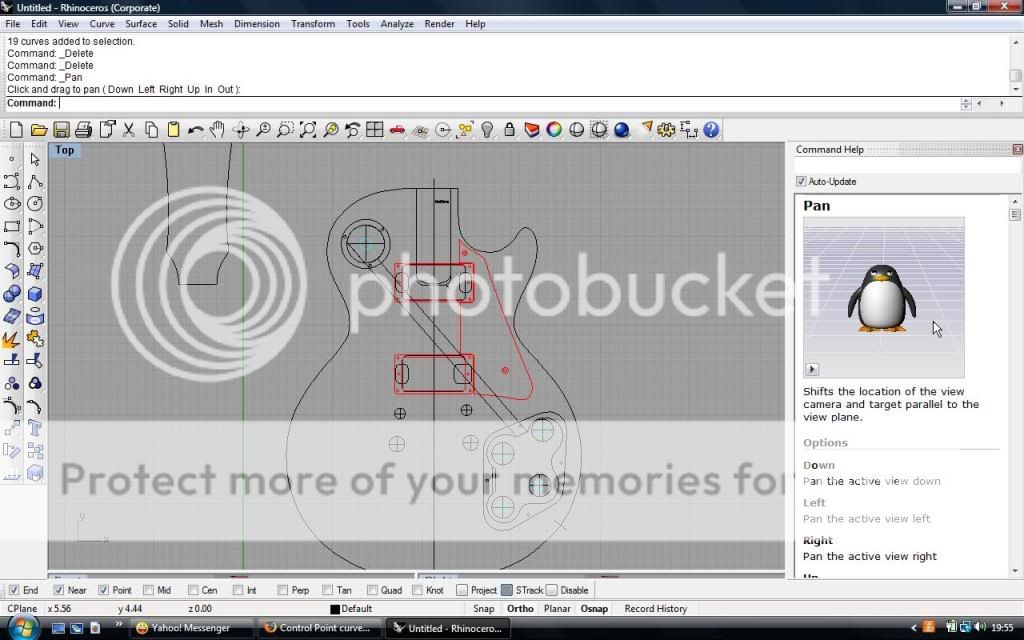
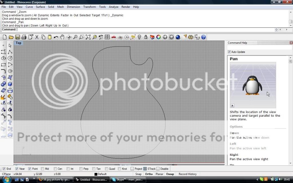
This is what I did and someone said that it doesn't look right
I was tracing a body shape with the freeform> interpolated points curve option on Rhino. However this person suggested I should use control points to form the shape like this:
and that the blue cutaway curve must have at least G1 curvature continuity, preferably G2, with the neck curve
However I find that the control point curve option is too hard to use and I need some advice on this subject
Thread: Control Point curves
Results 1 to 5 of 5
-
02-12-2010, 12:27 AM #1
 Registered
- Join Date
- Feb 2010
- Posts
- 0
Control Point curves
-
02-12-2010, 03:30 PM #2
Registered
- Join Date
- Aug 2006
- Posts
- 133
A spline curve in Rhino can be constructed and modified by using either a control point curve or an interpolated points curve (edit points). They both result in a spline curve (nurbs).
The 2nd picture you posted looks excellent; very simple where it needs to be and more detail where you need it. If that isn't your work and you are trying to replicate it, they have given you the answers on where the control points need to be placed You can simply make a curve by clicking on the curve in the background image in the appoximate area of the control points shown with the same starting and ending points. Use a pointsOn command to show the control points and drag them to make your curve match the background with the points in the areas shown. The flat area on top for the neck interface would be a straight line. There would also be an angled line following the FB profile at the top of the blue curve that needs to be accurately placed first, then you can do another control point curve to trace the cutaway. The red one is either another tracing or maybe a blendcrv that's been rebuilt/tweaked. You need to check the geometric continuity of your seams and use the match command. If this all sounds like gibberish you should spend some time with the manuals and tutorials on the red cd first then it will make more sense.
-
02-12-2010, 09:43 PM #3
Registered
- Join Date
- Feb 2010
- Posts
- 0
The 2nd picture is not my work. I've tried importing the image as a background image but the image became too blury for my liking. The guy who made the 2nd picture models guitars for a living so that is why it is 'excellent'.
So could I achieve a nice smooth curve like this using the interpolated points curve option - particularly at the horn and at the cutaway? I would like to avoid the control point curve option as much as possible.
Since posting this I've had an idea. The first picture is my attempt, and u can see that the continuity is probably G0 with the straight neck pocket bit.
I'll show u exactly what I've decided to do to achive the basic guitar body model so u can help me
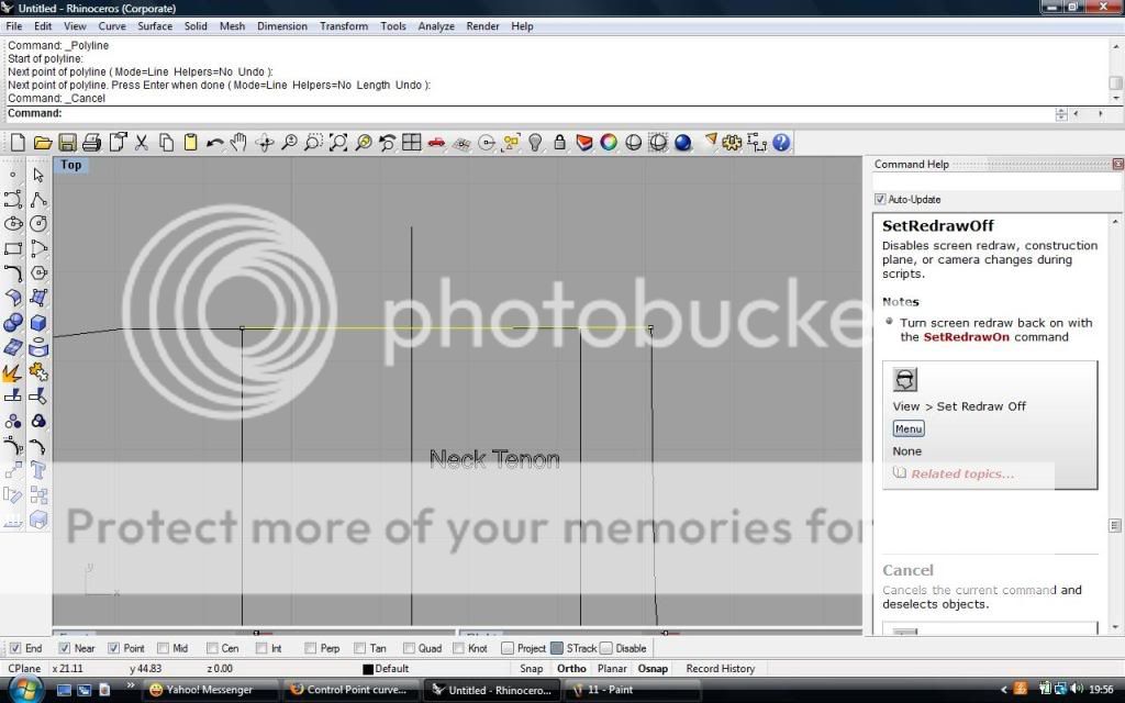
First I import the body plan I wish to trace. Note the outline of this guitar cannot be used as it is discontinous and thus it must be traced.
For reference this plan is known as the John Catto plan ( I deleted of some of the headstock stuff and the inlay outlines)
I then place two points at the ends of the straight part of the neck and join them with a line
I then place a point nearby the line
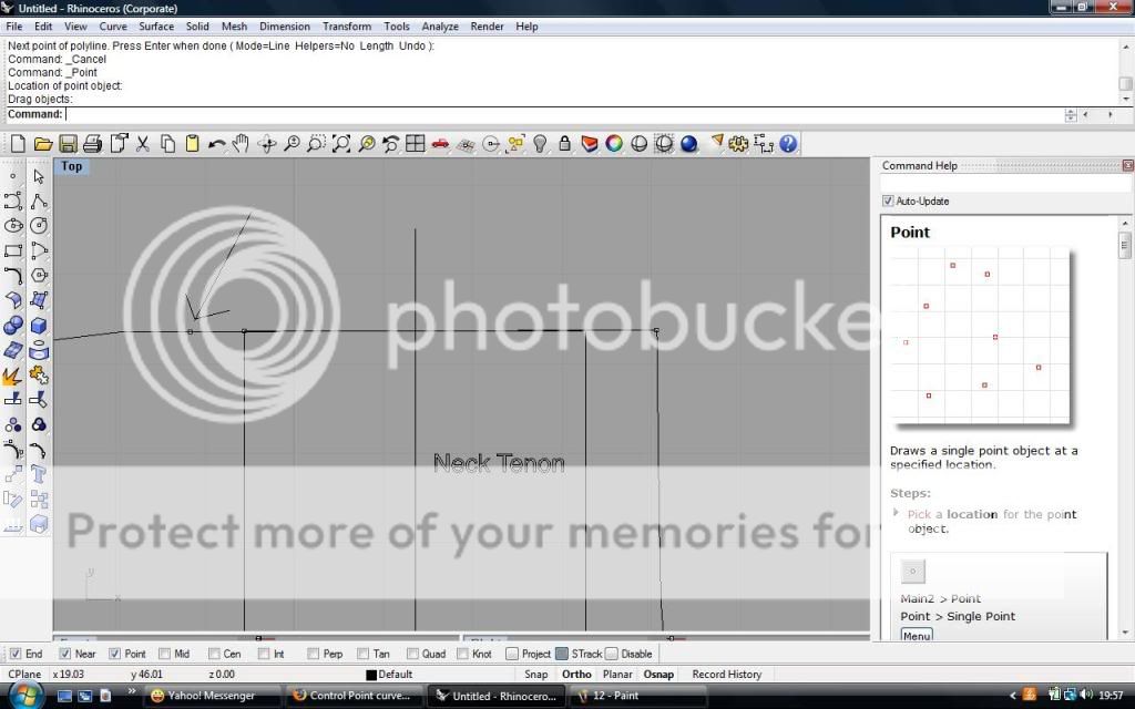
I then draw my curve using the interpolated curve option, and using the nearby option to help me trace. This curve joins the other side of the straight line where it make a 90 degrees angle to it. I also delete the original curve so I can see what I am doing

I then use the blend function to blend this curve into the line
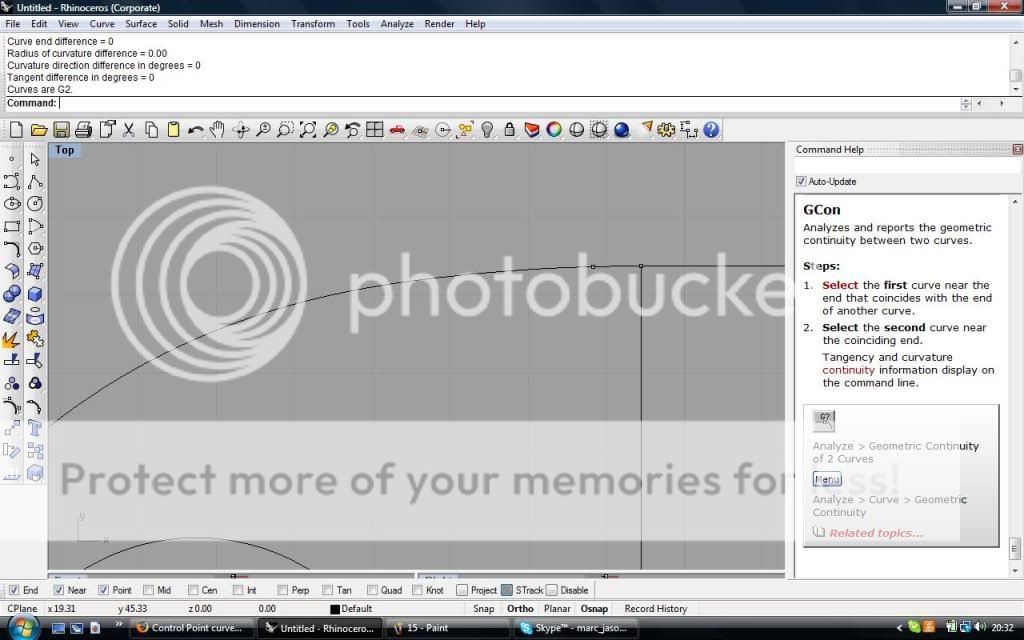
I have G2 at this point
Here is a zoomed out pic
Will it be ok for the rest of the steps now?
-
02-13-2010, 03:56 PM #4
Registered
- Join Date
- Aug 2006
- Posts
- 133
If you lock the layer, or select the curves and lock the curves, containing the imported geometry that you want to trace you can still use snaps but it will not allow you to select the locked curves. Do you tracing on another layer. Surfaces etc on another.
Rhino has a lot of different types of object snaps so placing points to help with constructing geometry usually isn't necessary.
Start rough and refine. If you turn on edit points instead of control points you can drag the endpoint of a curve/line to a new location. Repositioning control points smoothly changes the section of curve under its influence. Repositioning an edit point changes the point the curve goes through which makes it more difficult to do smoothly. A blend makes a new curve. Use match when you want to adjust the continuity of one curve to another. Blendcrv lets you have different continuity on one end than the other which sometimes is needed.
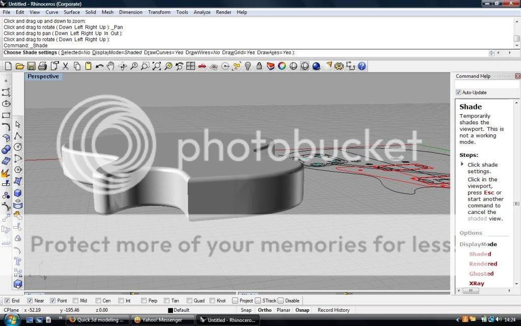
What you did is probably fine but not sure what you are trying to do. The rule is always inspect. Your first posted extrusion has what looks like ripples or distortion in the sides surfaces. Get to know the analysis commands. You can have a window set to render mode (right click the title like perspective and choose rendered). Different colors and lighting (layer manager materials and reflectivity) help to reveal surface quality too. If it looks funny change the geometry and try again.
-
02-18-2010, 10:26 PM #5
Registered
- Join Date
- Feb 2010
- Posts
- 0
I've documented what I've done so far here if your interested:
http://www.mylespaul.com/forums/luth...-tutorial.html
The threads a but messy as it evolves as I learn new bits of information


 Reply With Quote
Similar Threads
-
Control Point curves
By LuptonM in forum Rhino 3DReplies: 2Last Post: 02-13-2010, 12:29 AM -
Use a point for the start point of a profile.
By dcskid in forum BobCad-CamReplies: 2Last Post: 03-18-2009, 04:31 PM -
How to control the starting point of a pocket
By journeyonline in forum BobCad-CamReplies: 4Last Post: 08-14-2008, 03:15 AM -
importing control point curves from rhino
By EvanB in forum BobCad-CamReplies: 1Last Post: 06-24-2008, 01:07 PM -
converting point to point programs
By kevinwd1 in forum Uncategorised CAM DiscussionReplies: 2Last Post: 06-11-2007, 05:45 PM
