


All the parts are off to anodizing. All the components for assembly have arrived. So assembly starts when the parts get back!
Results 61 to 80 of 99
-
09-15-2019, 03:17 AM #61
 Member
- Join Date
- Feb 2005
- Posts
- 829
Re: CRP4896 Standard to Linear Rail Conversion
-
09-15-2019, 10:21 PM #62
Member
- Join Date
- Apr 2016
- Posts
- 841
Re: CRP4896 Standard to Linear Rail Conversion
 Originally Posted by nlancaster

Can't wait to see how the anodizing comes out. Hope all goes well with installation of the linear rails. Lots of pictures, please.
Gary
-
09-24-2019, 05:19 AM #63
Member
- Join Date
- Feb 2005
- Posts
- 829
Re: CRP4896 Standard to Linear Rail Conversion
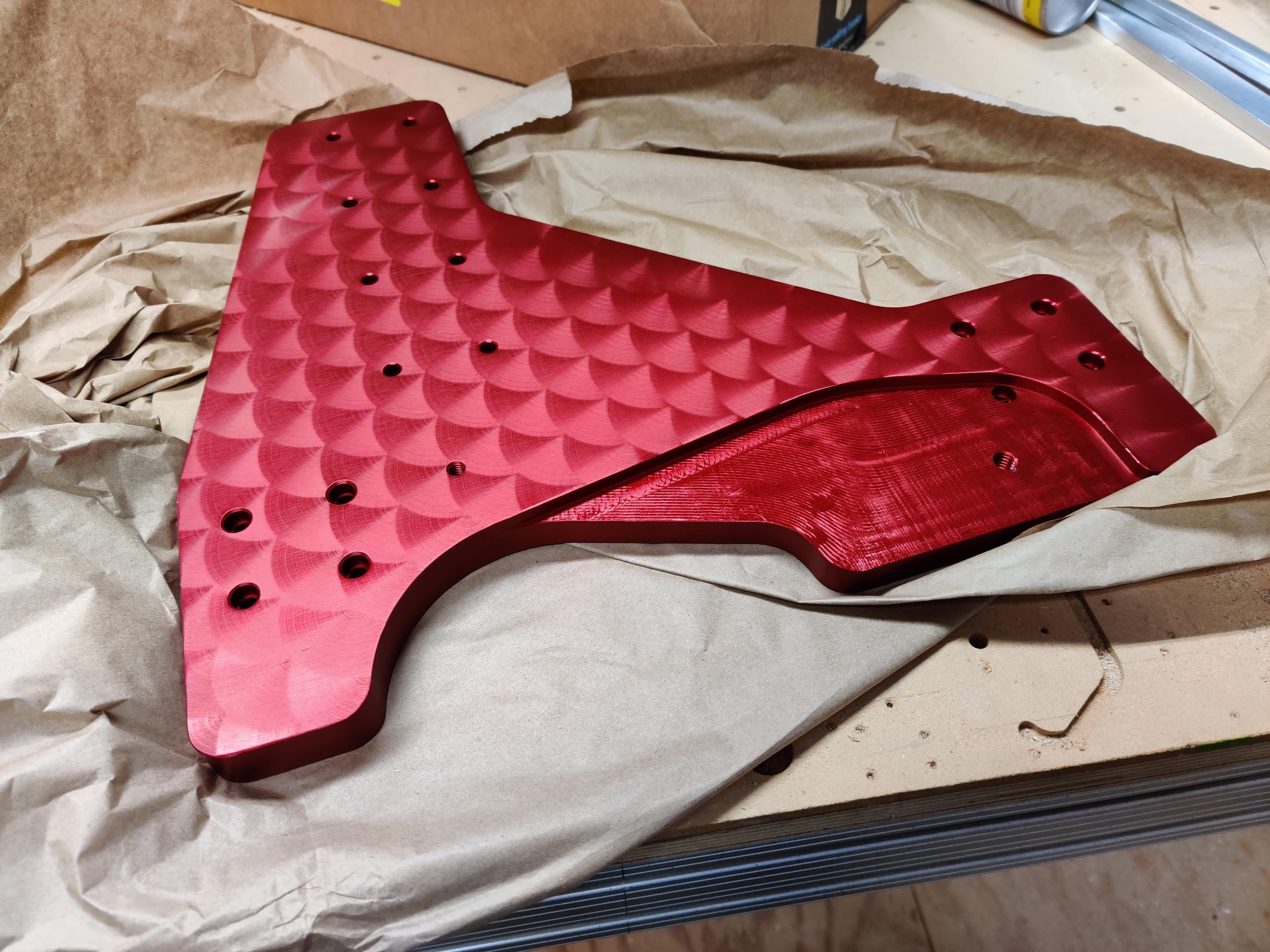
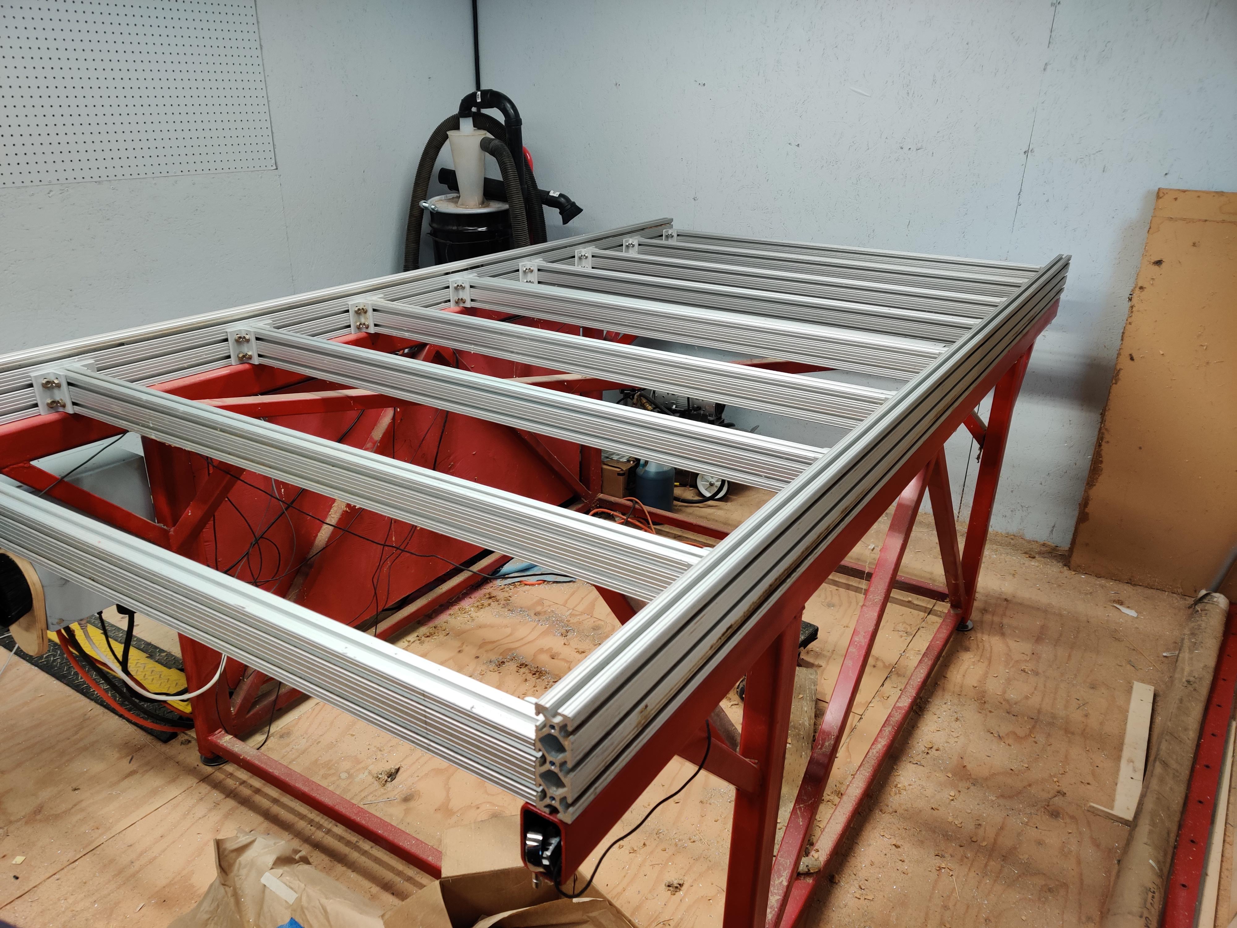
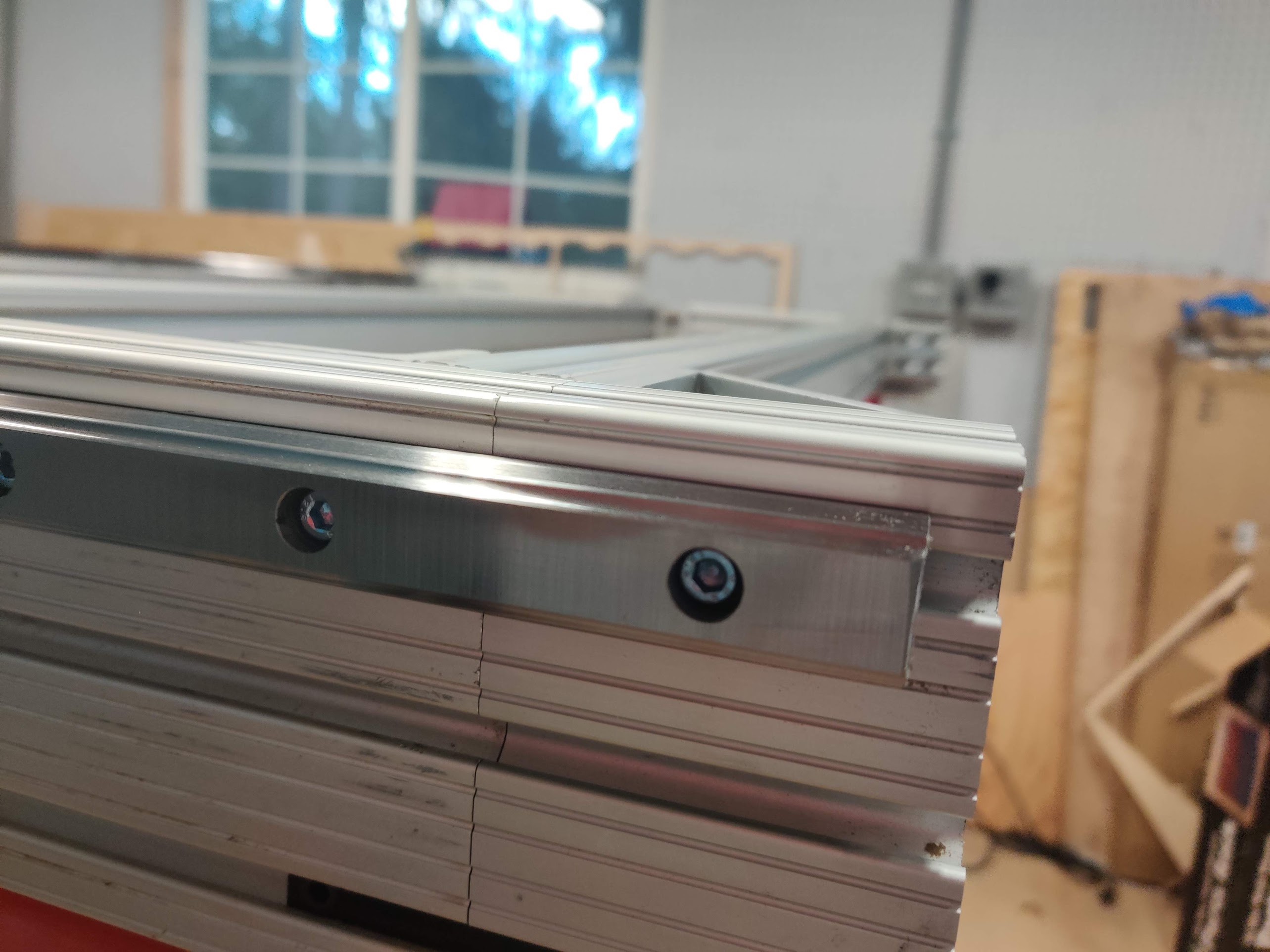
Parts are back from anodizing..... BLING!
-
09-25-2019, 05:09 AM #64
Member
- Join Date
- Apr 2016
- Posts
- 841
Re: CRP4896 Standard to Linear Rail Conversion
Bling indeed. Very nice. The texturing looks great!
Gary
-
09-25-2019, 05:39 AM #65
Registered


- Join Date
- Jan 2007
- Posts
- 626
Re: CRP4896 Standard to Linear Rail Conversion
Very nice! Originally Posted by nlancaster
Sent from my SM-G920I using Tapatalk
-
09-29-2019, 01:41 AM #66
Member
- Join Date
- Feb 2005
- Posts
- 829
Re: CRP4896 Standard to Linear Rail Conversion
Disassembly complete!
Before -
After -
-
10-05-2019, 01:31 AM #67
Member
- Join Date
- Feb 2005
- Posts
- 829
Re: CRP4896 Standard to Linear Rail Conversion
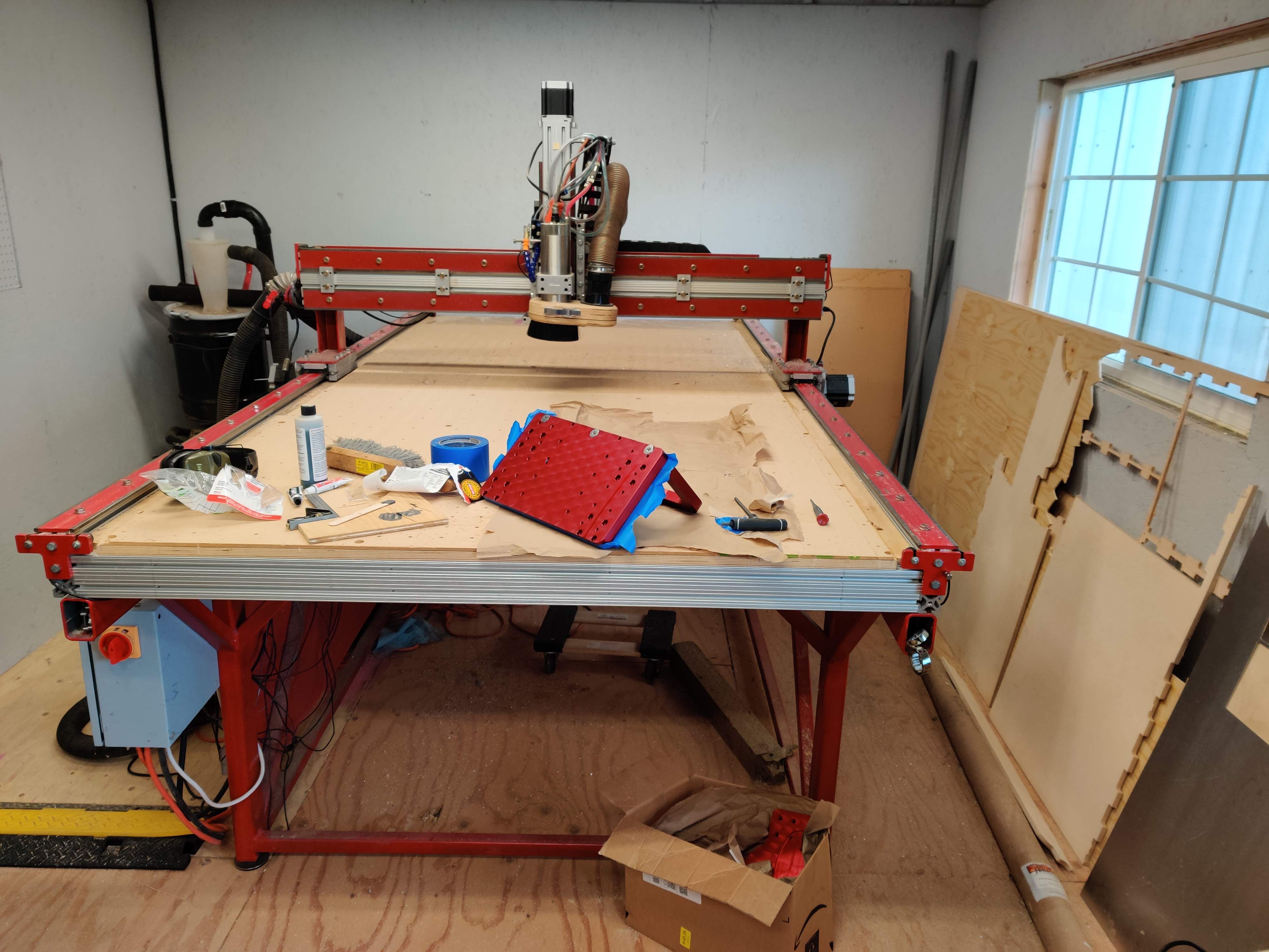
started reassembly today.
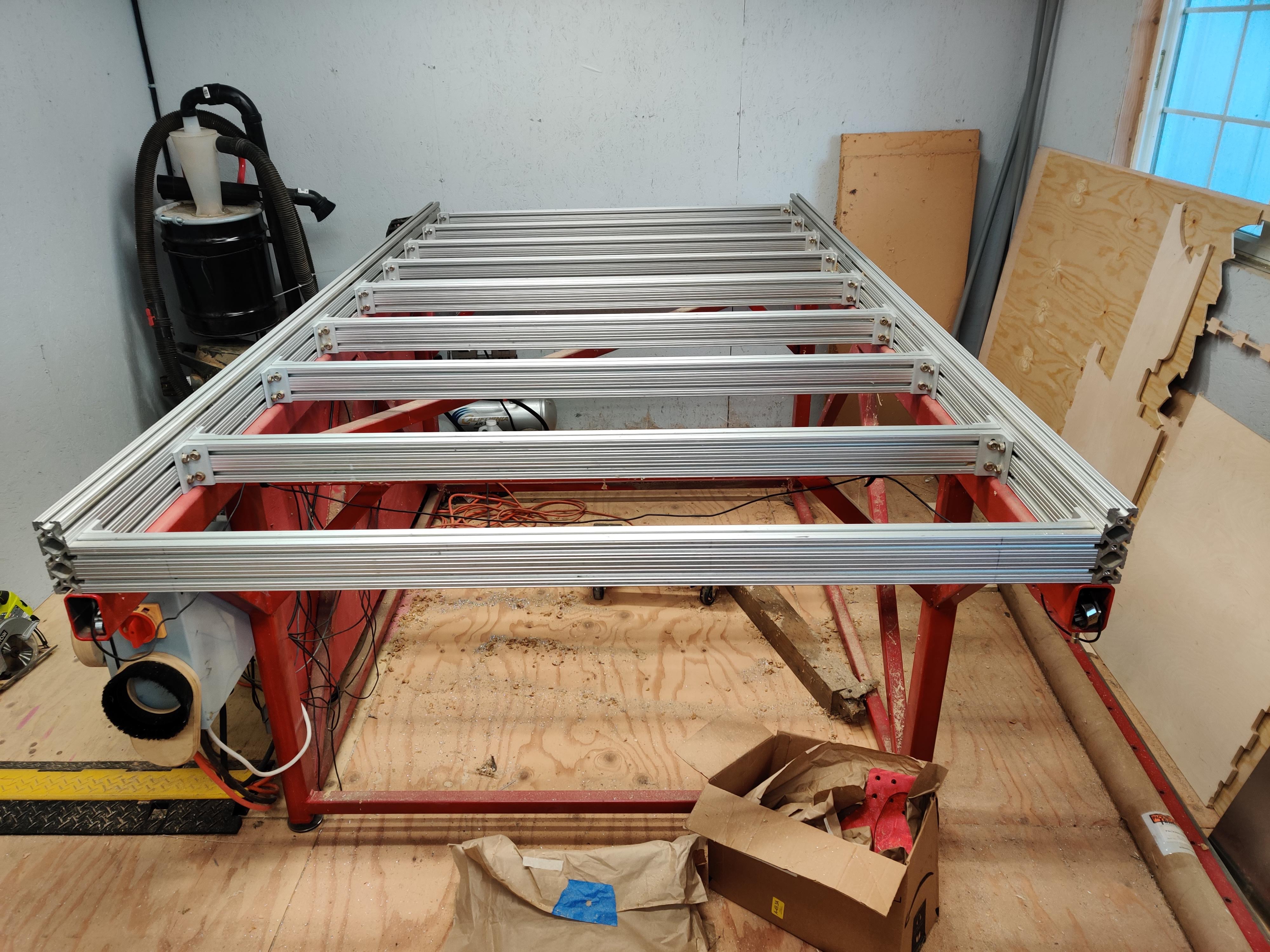
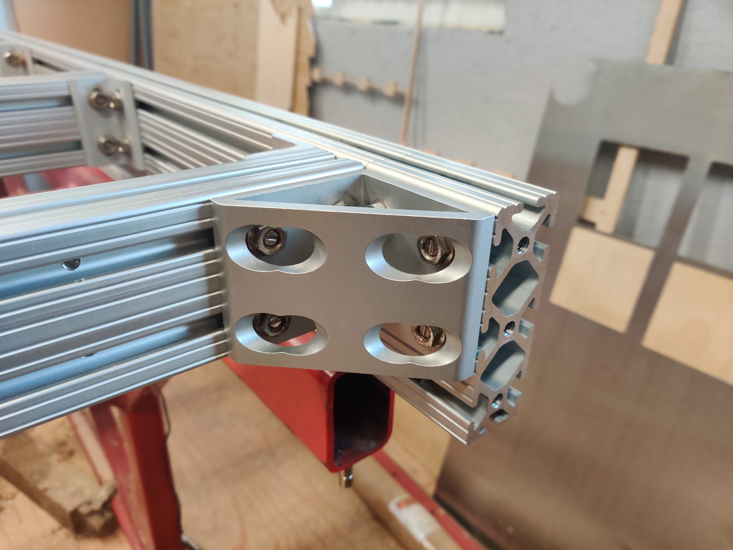
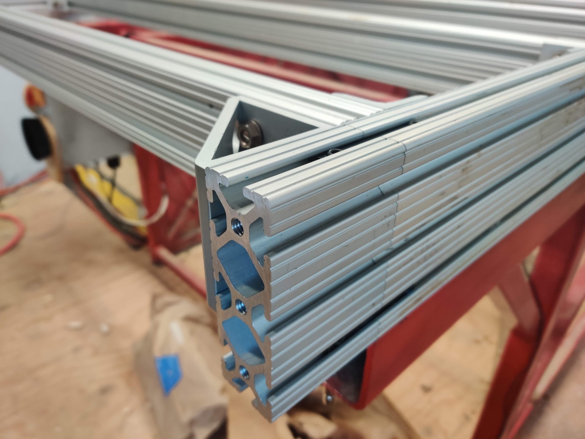
Flipped the extrusion table over, so that all the beams are level at the top.
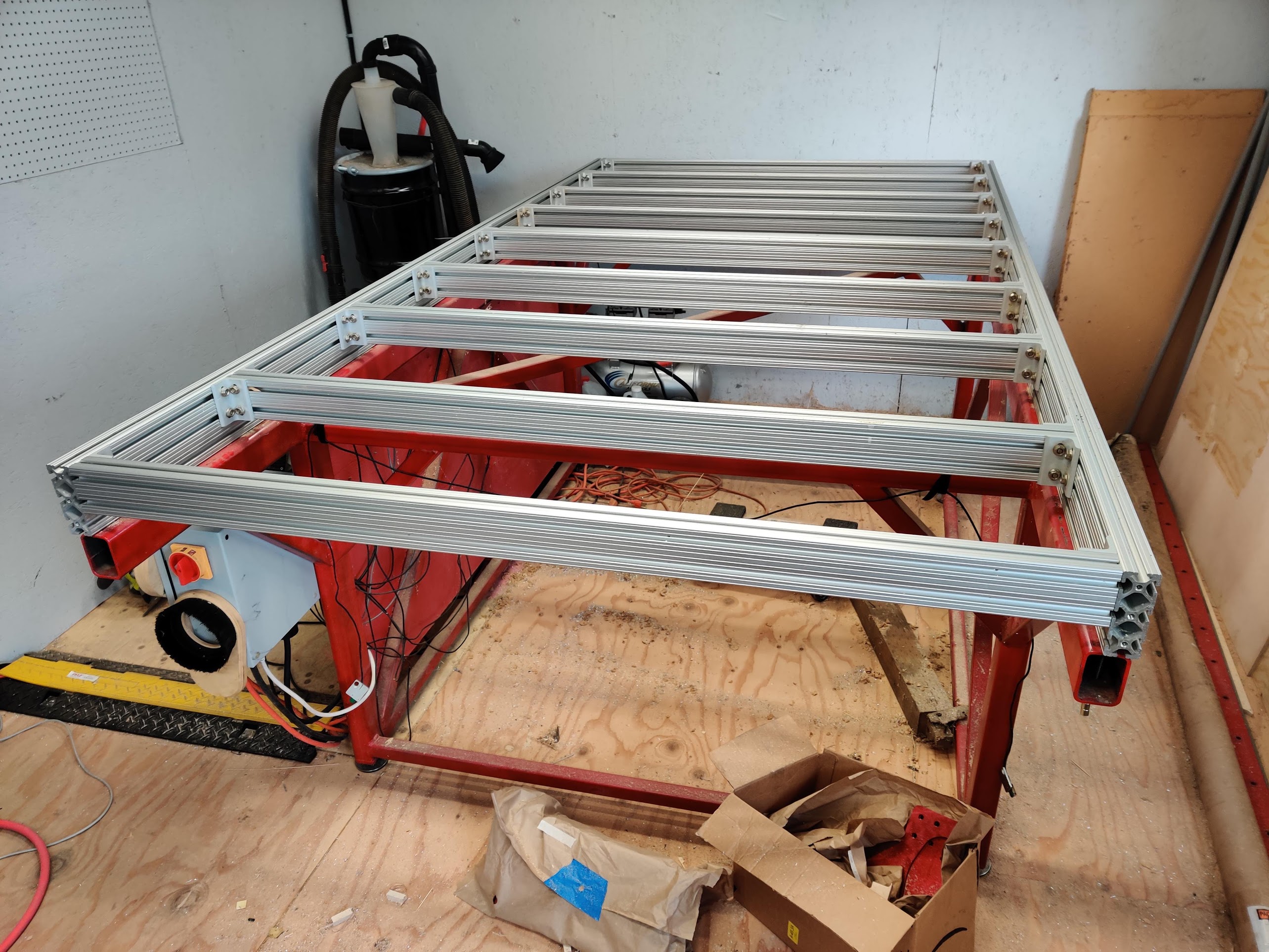
Installed the extrusion extensions, these are on all 4 corners to get me a 12 inches of separation on the linear carriages on the y-axis.
Installed both y-axis linear rails, these are BLH linear rail from automation overstock, they do appear to be ground quite nicely on the actual ball surfaces. But the top and bottom surfaces do have what appears to be a very course sanding/grinding applied to them, smooth to the touch but with noticeable lines in it. I did temporarily install one carriage and it ran smooth with no grinding or even making very much noise either.
-
10-06-2019, 11:23 PM #68
Member
- Join Date
- Feb 2005
- Posts
- 829
Re: CRP4896 Standard to Linear Rail Conversion
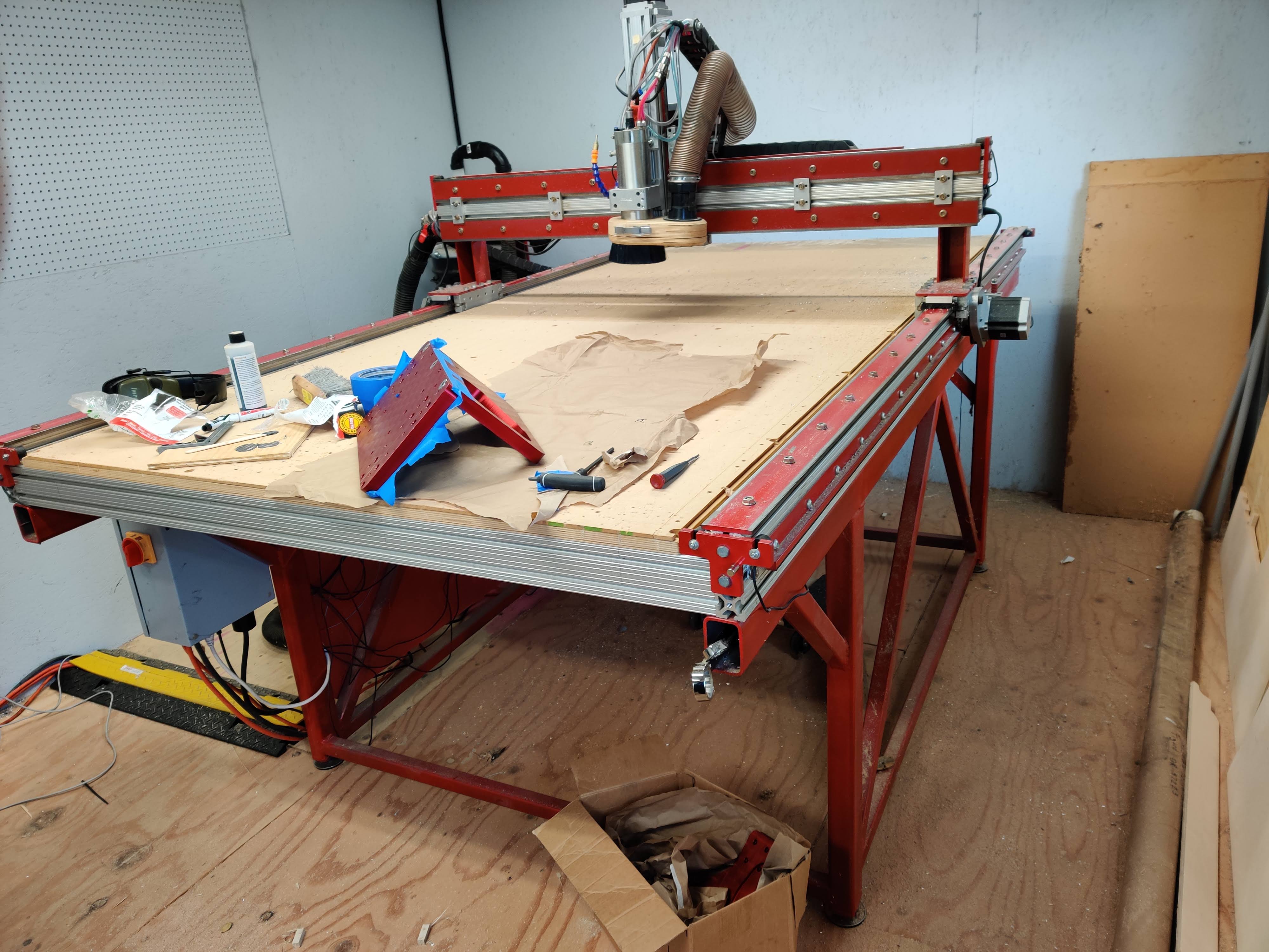
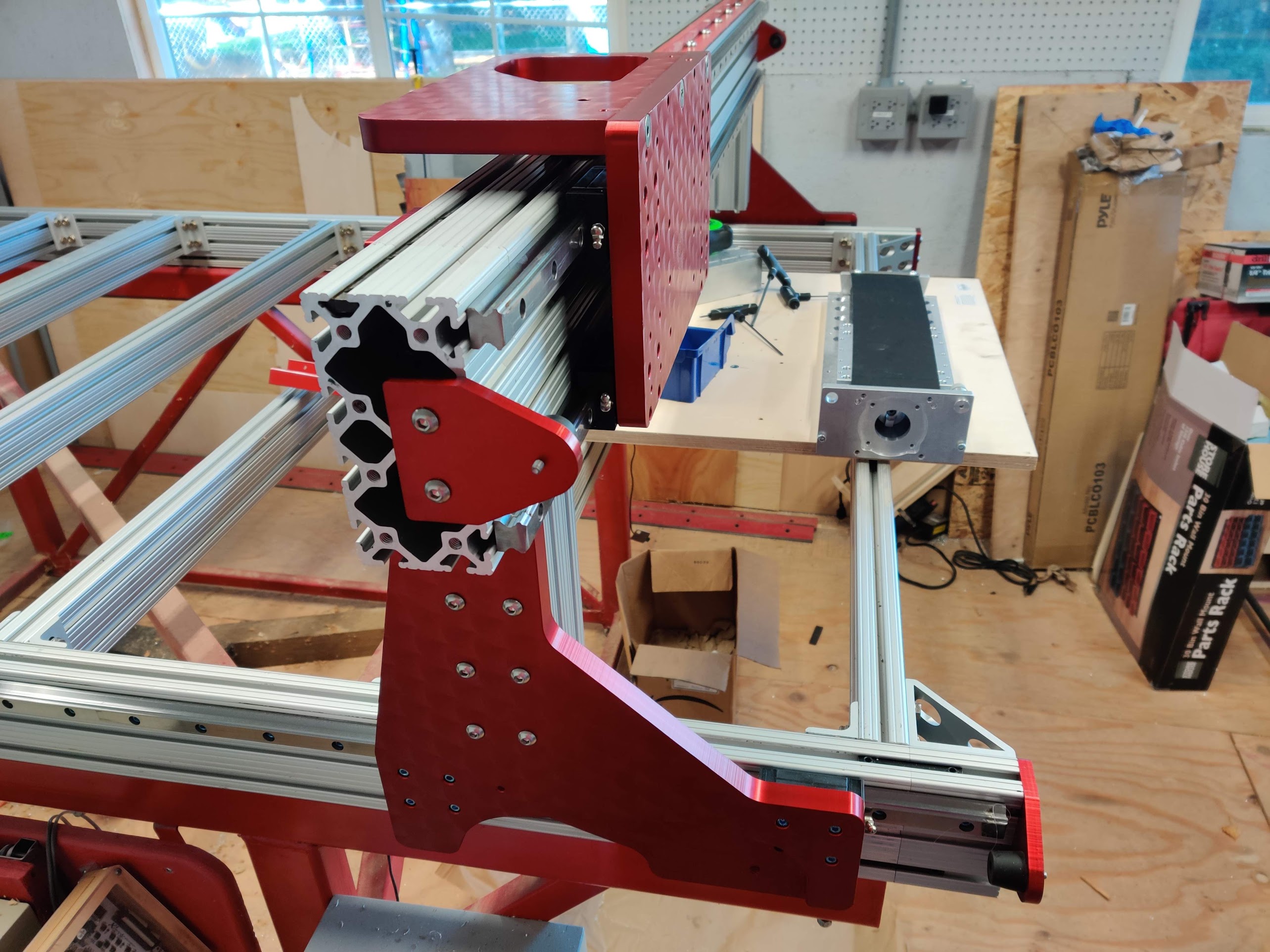
So this weekend got the rails and gantry assembled.
And then ran into a problem, somehow I ended up with my z-axis bolt pattern 5 inches wide, but the actual pattern is only about 4.75inches wide.... no idea how I managed this, working a couple options to fix it.
-
10-07-2019, 05:19 PM #69
Registered
- Join Date
- Apr 2004
- Posts
- 326
Re: CRP4896 Standard to Linear Rail Conversion
Do you have a link to a source for the pad (assuming its foam and compresses easily?). Can't find anything easy. Thanks. Also, any spindle holder is good for that? Looks like you have 1/2" shaft there. Originally Posted by nlancaster
-
10-08-2019, 05:12 AM #70
Member
- Join Date
- Feb 2005
- Posts
- 829
Re: CRP4896 Standard to Linear Rail Conversion
the pad holder was just a good flat holder, 1/4 shaft.
Here were the pads I used, https://www.amazon.com/gp/product/B0...?ie=UTF8&psc=1
-
10-11-2019, 10:13 PM #71
Member
- Join Date
- Feb 2005
- Posts
- 829
Re: CRP4896 Standard to Linear Rail Conversion
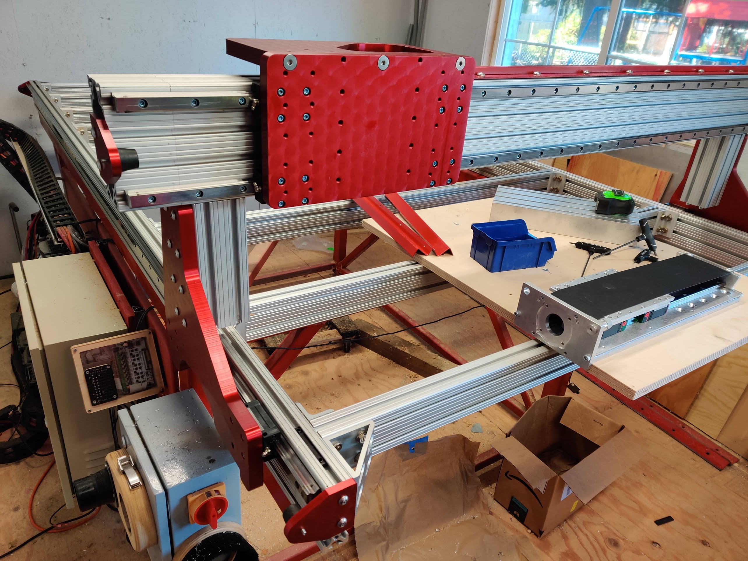
An aquaintance helped me mod the z-axis mounting plate. We just drilled new holes and countersunk them apropriately now it mounts up just fine!
All major mechanical reassembly is complete! Now just need to remount the Steppers, limit switches, spindle and cable chain.

-
10-14-2019, 01:49 AM #72
Member
- Join Date
- Feb 2005
- Posts
- 829
Re: CRP4896 Standard to Linear Rail Conversion
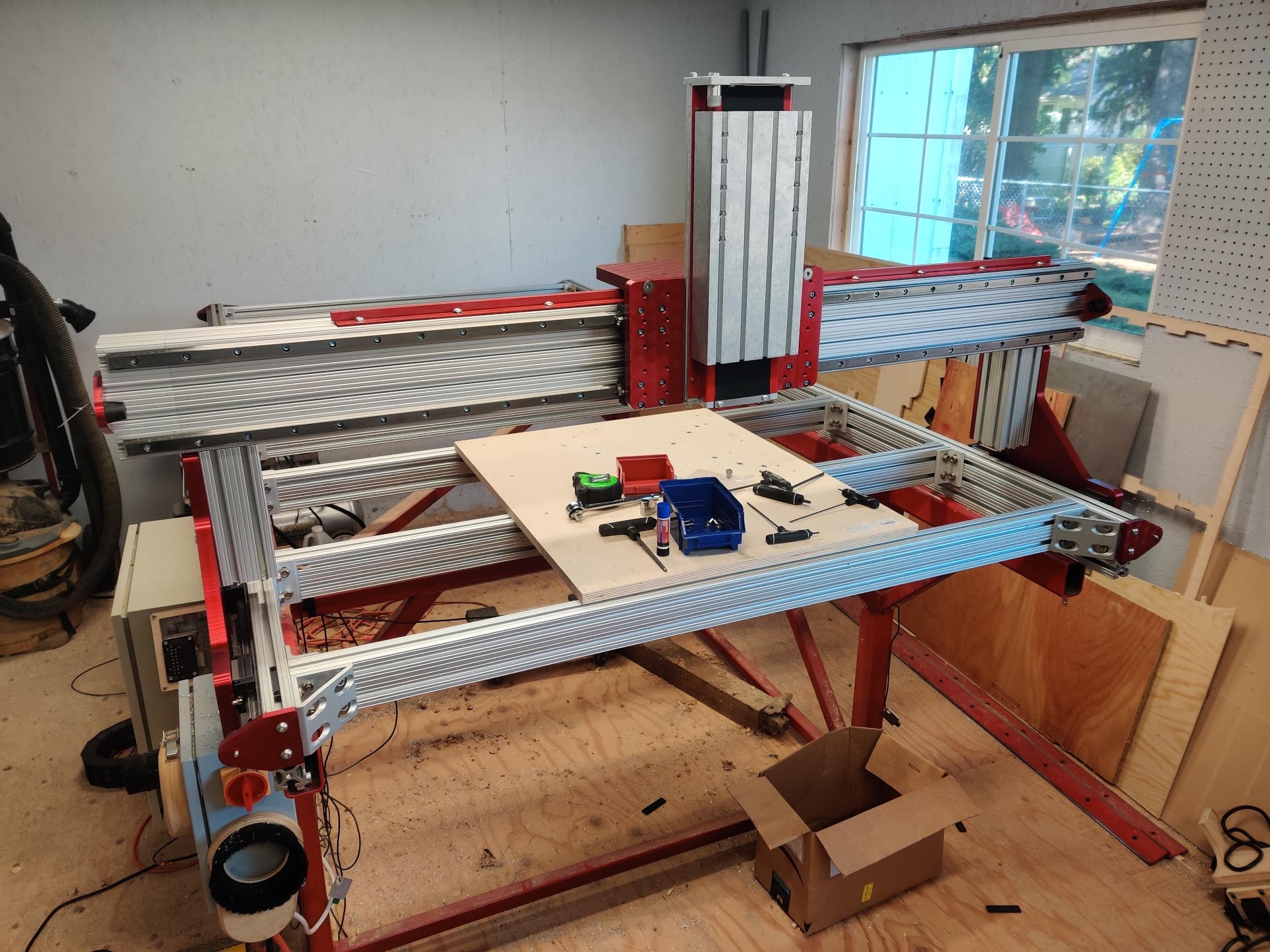
IT'S ALIVE!!

Finished all major mechanical assembly, just need to setup the limit switches, table and tune the machine!
https://youtu.be/iuPB33bhkkM
-
10-15-2019, 05:51 AM #73
Member
- Join Date
- Feb 2005
- Posts
- 829
Re: CRP4896 Standard to Linear Rail Conversion
Did interest in this die? Had several people posting, and now that I am getting pictures up.... crickets.

-
10-15-2019, 04:55 PM #74
Member
- Join Date
- Apr 2016
- Posts
- 841
Re: CRP4896 Standard to Linear Rail Conversion
Originally Posted by nlancaster
I'm still watching. I'm curious about the technique you used to position the linear rails. The current Avid kits use what they call a "rail alignment jig" to set the rails at each end and at the splice. Apparently, they use the jig at the splice because they use 2 pieces of linear rail for each side of the Y axis. There is a potential problem with the technique: Linear rails have no spec for straightness and may, in fact, not be perfectly straight along the length. Also, it doesn't take much to flex them by several thousands. Add to this the potential for the extrusions not being perfectly level along the length and chance of some degree of misalignment increases. How did you address all the variables?
Gary
-
10-15-2019, 06:35 PM #75
Registered
- Join Date
- Jan 2015
- Posts
- 194
Re: CRP4896 Standard to Linear Rail Conversion
I’m watching so please continue to share. Originally Posted by GME
And I used their jig in a few places since I have a 10’ machine with no rail splices but my machine is not flat across its length. I should probably adjust at some point but to this point I haven’t. Then again, also not sure of the best way to flatten it as I don’t have a flat reference to work with.
-
10-16-2019, 12:31 AM #76
Member
- Join Date
- Apr 2016
- Posts
- 841
Re: CRP4896 Standard to Linear Rail Conversion
David, Originally Posted by dgage
Here's a technique for measuring flatness that mactec54 wrote in one of my threads.
"A simple small roll of piano wire ( .020 Dia or similar can be smaller dia ) and feeler gauge set is all you need, you need to make a fixed block for one end of the piano wire, and the other mounting block so you can tension the wire, both blocks are fixed mounted by bolting or clamping, they must be rigidly mounted, this is simple and can be very accurate within .001 can be achieved
When making your adjustable side for tensioning the piano wire, think of a simple tuner like on a guitar can be just a bolt to wind up the wire"
This would allow you to establish a reference surface.
Maybe you should start a thread and provide detailed information (with pics) on your setup. I'd bet some folks here on the Zone would have some good suggestions.
Gary
-
10-16-2019, 12:51 AM #77
Registered
- Join Date
- Jan 2015
- Posts
- 194
Re: CRP4896 Standard to Linear Rail Conversion
Thanks Gary! That sounds simple and effective.
-
10-16-2019, 01:34 AM #78
Member
- Join Date
- Feb 2005
- Posts
- 829
Re: CRP4896 Standard to Linear Rail Conversion
GME i used the avidcnc block style, but a screw with jam nut in a threaded hole to set the depth. The linear rail is straight to within .002 over its length to the best of my ability to measure using a machinist straight edge and dial indicator.
-
10-19-2019, 06:54 AM #79
Member
- Join Date
- Feb 2005
- Posts
- 829
Re: CRP4896 Standard to Linear Rail Conversion
All the limit switches are connected, now the tuning can start.
-
10-29-2019, 03:27 AM #80
Member
- Join Date
- Feb 2005
- Posts
- 829
Re: CRP4896 Standard to Linear Rail Conversion
Spent Friday and Saturday installing table and squaring machine up, it is as square as I can make it.
Bored holes in baltic birch subtable, and installed 64 1/4-20 threaded inserts for clamping in the front middle of table.
https://youtu.be/1487keBiCgw

 Reply With Quote
Similar Threads
-
HF 8x14 linear rail conversion....and maybe more...
By CS900 in forum Mini LatheReplies: 99Last Post: 08-10-2022, 02:12 PM -
Standard linear motion conversion to linear rails.
By bobmagnuson in forum Avid CNCReplies: 11Last Post: 03-25-2022, 09:52 PM -
G0704 Linear Rail Conversion
By BTP in forum Benchtop MachinesReplies: 63Last Post: 07-14-2019, 01:59 AM -
Sieg X3/SX3 Linear rail conversion
By DvG4 in forum Benchtop MachinesReplies: 1Last Post: 01-16-2011, 02:17 AM -
Mixing Preloaded&Standard linear trucks on same rail -pros and cons ?
By isvflorin in forum Linear and Rotary MotionReplies: 2Last Post: 01-13-2009, 06:05 PM
