


Greetings all. This is my first post, though I have been lurking on this forum for awhile admiring all of the CNC builds. A truly impressive variety of creative solutions to CNC!
I am undertaking the design of my first DIY CNC Router. Though this is my first router project, I do have a lot of machinist experience and I have built a fair number of motion control rigs over the years for film and TV work. My goal is to build a medium size, bench top machine that will fit within a 3 foot by 4 foot area (size restrictions in my shop). I already have some linear motion components lying around from old motion control projects so I will integrate those the best way possible.
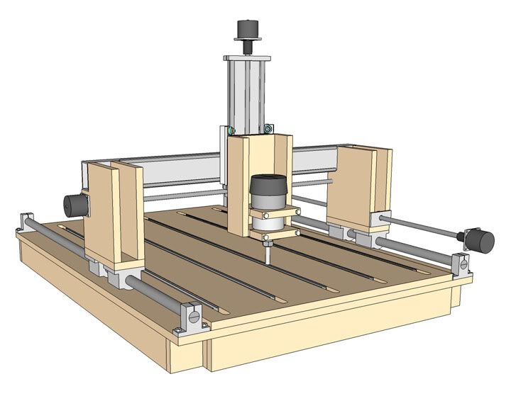
My biggest indecision is whether to go with a spanning torsion table design, like the JGRO or a simpler design where there is no connection between the Y axis linear bearings. Attached are two designs I've worked out (they are still works in progress, there are a lot of missing details, like motor brackets). The first is based on the JGRO, modified to fit my space and using the linear components I have on hand. The second is the non-spanning table design.
My biggest question is this, am I likely to run into problems trying to drive the Y axis on the second design from only one side? I'll be using 1 inch precision linear rails and bearings. Are gantries built with these as prone to wracking problems as V bearing designs? I suppose I could put drive screws on each side and connect them with a belt but that's a lot of work.
Any advice on the pros and cons of each option would be much appreciated!
Thread: Design Advice Needed
Results 1 to 20 of 21
-
09-09-2010, 09:16 PM #1
 Registered
- Join Date
- Jul 2010
- Posts
- 0
Design Advice Needed
-
09-09-2010, 11:02 PM #2
Registered
- Join Date
- Sep 2010
- Posts
- 0

You are buying yourself a lot of grief if you try to move the carriage from only one side. It will tend to bind when moving in both directions. If by some chance the carriage does not bind (say the bearings are spaced far enough apart), you will definately skew the carriage enough that you will always have the non-driven side lagging behind the driven side. Center driven is best though you could always drive both sides as in a master slave arrangement. Hope this helps.
-
09-10-2010, 02:31 AM #3
Registered
- Join Date
- Aug 2008
- Posts
- 409
Some suggestions from me,
X axis using unsupported ways, I highly suggest you use supported ways, I made that mistake on my machine and its greatly limited my speed and cutting capacity, I am constantly fighting the flexing shaft, it will flex! I am kicking myself for not using supported rod or rails.
I like the design of the non spanning table design, the other one you will have problems with the table sagging.
Your Z axis is much too tall, its going to be a huge lever and will flex alot. I suggest you redesign your Z, make it as compact as possible, the majority of tooling only coming in a max 2" cutting depth, so really you only need 4-6" of travel depending on what you want to cut.
I cant clearly see how your Y/Z carriage works, any better angles?
Dont drive your X axis from only one side, it will rack, use a dual drive system or a center drive. Using two motors for an X would be ideal IMO.
As for the Y, it may work from one side, but I would try to center it, I have my Y leadscrew closer to my bottom bearing but still in between the two.
Try to widen the Y bearing spacing, the grey rectangle that spans the Y axis, make it wider.
-
09-10-2010, 05:41 PM #4
Registered
- Join Date
- Jul 2010
- Posts
- 0
X and Y
Thanks for the initial advice guys. The more I look around, the more I like the idea of the non-spanning table design, even if it means driving it from both sides, either by using dual motors, or a timing belt.
For clarification, is there a standard for which axis is called X and which axis is called Y? I've seen it done both ways?
-
09-10-2010, 05:47 PM #5
Registered
- Join Date
- Aug 2008
- Posts
- 409
X axis is usually the axis that the gantry rides on, Y axis rides on the X.
Z axis is the vertical axis.
This makes the most sense to me. XYZ Y is after X. Y rides on X.
Some people mix up the X and Y.
-
09-10-2010, 06:01 PM #6
Registered
- Join Date
- Aug 2008
- Posts
- 1166
Dual motors driving the x are better than a single center motor imo. The single center motor will be slewed by the router cutting anywhere but in the center. You will also get slewing when you rapid if the router is not centered. These forces are usually more manageable than if you drive the gantry from only one side, but they're still there. If you drive the gantry from both sides you have a much more rigid system. The only time you have a problem is if you stall one stepper motor but not the other, but due to having two motors pushing, this is probably less likely than stalling a single motor with the other designs which would also cause problems. It's also really helpful to set up dual home switches so you can square your gantry while homing.
-
09-10-2010, 06:11 PM #7
Member
- Join Date
- Apr 2007
- Posts
- 8082
From an electrical and software perspective you can assign any motor any axis letter you want to. From a real world perspective if you don't have some sort of standard configuration you may have some surprises when you run someone else's gcode. That's why you should always run the code in simulation mode or "cut air" to see which way things move.
For instance, there are machines that have a gantry that is wider than the front to back travel on the non-moving axis. They sometimes call the gantry the X axis on these "wide routers". That's why you can't just assume that the X axis is always the longest travel axis. If I built one of these myself I would still call the gantry (moving or fixed type) the Y axis.
CarveOneCarveOne
http://www.carveonecncwoodcraft.com
-
09-10-2010, 08:23 PM #8
Registered
- Join Date
- Mar 2007
- Posts
- 398
Phife have to agree.
I got 25mm rails and thought meh they will be ok over 1m yeah right had more flex than a gymnast.
I got around it easily though please look up for my thread and see the way I supported them.
Though on the X axis the supports are not screwed into the rails this wont be a problem unless I take one huge ass plunge which wont happen as it weighs a lot my gantry so still wont lift any way
-
09-11-2010, 08:06 AM #9
Registered
- Join Date
- Jul 2010
- Posts
- 0
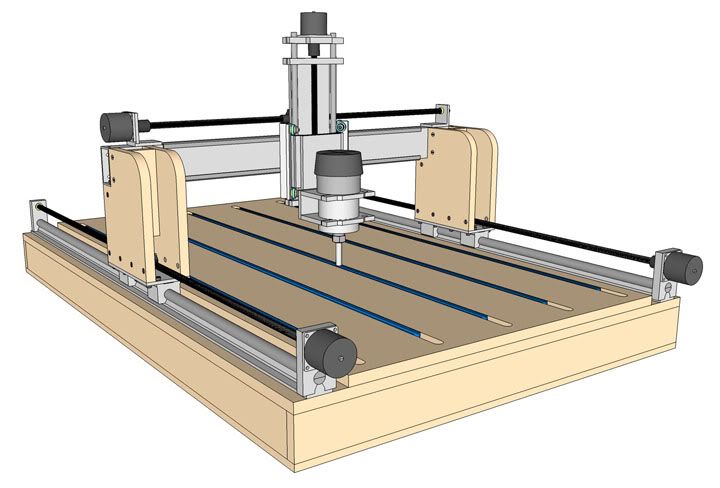
Again thanks for all the input guys! I've decided to go with the a non-spanning table design and drive the gantry from both sides, either with dual slaved motors or a timing belt/chain connecting the lead screws. Here are a couple of views of the revised design. Based on the input here, I've shelved the idea of using the un-supported linear rail I had lying around for the X axis and instead have bought some fully supported rail and pillow blocks on EBay.
Based on the advice here I've also shortened the Z axis and lowered the Y axis. The stepper motor and lead screw for the Y axis have been moved to the top and now attach directly to the Y axis rather than the MDF gantry legs.
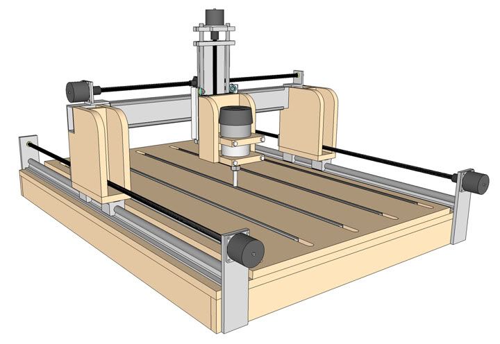
The Y axis is made from Dual-Vee components on 2" x 4" rectangular aluminum tubing. I'd like more distance between the rails, but this unit is something I've already got lying around, and it's pretty solidly built so I'm hoping the Z axis won't wrack on it from the off balance of the router. If it's a problems, I can always try to counter balance the router with some weight off the backside. Here's a rendering with some of the components hidden that shows the Y axis a little better.
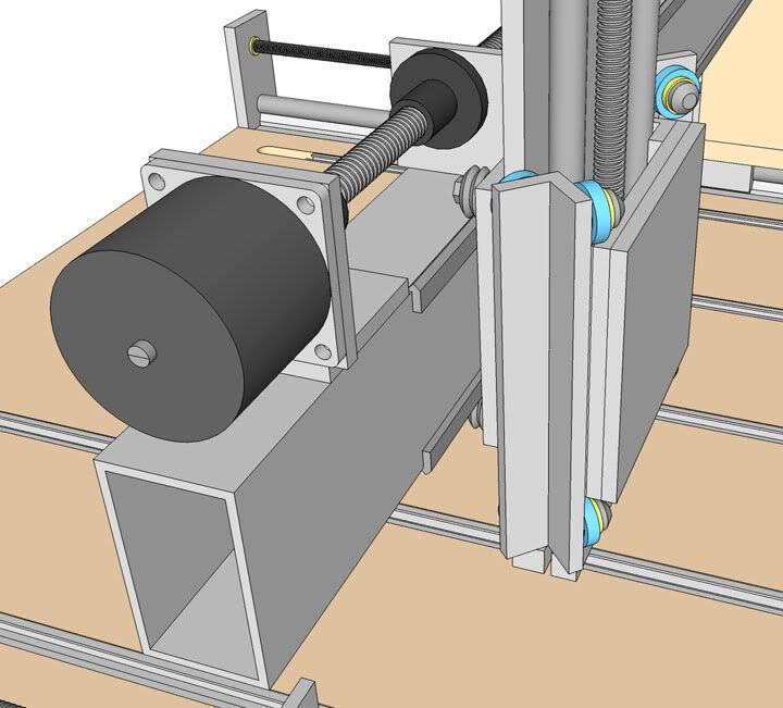
The Z axis is another pre-existing mover from old projects. It uses skateboard bearings riding along the outside of 1/2" rails. It's also pretty solid and should work well. The 3D model doesn't show all of the nuts and bolts that hold it all together and hold the bearings in compression against the rails.
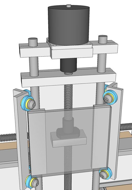
I'm planning to uses 1/2" acme precision threaded rod with anit-backlash nuts to drive all three axises.
With any luck I'll be able to move this thread over to the "Build" forum soon!
-
09-12-2010, 10:11 PM #10
Registered
- Join Date
- Jul 2010
- Posts
- 0
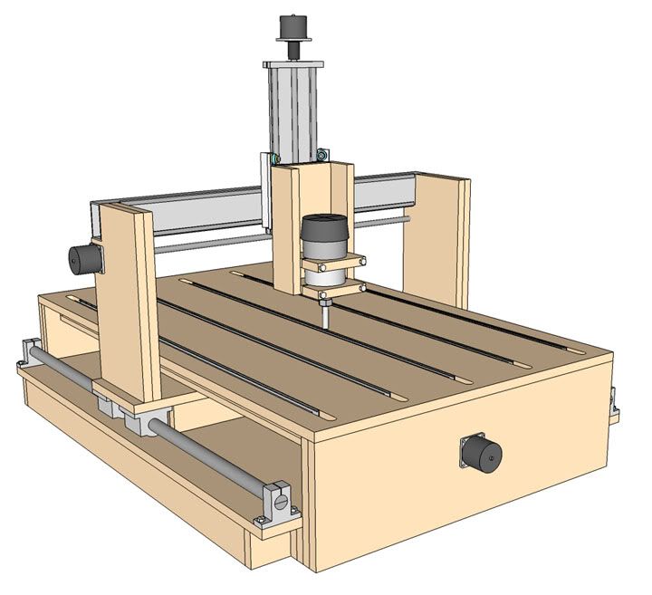
Ch, ch, changes...
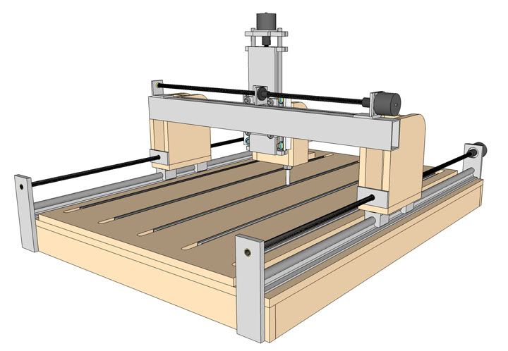
Further design refinements.
I changed the material for the plate to which the X axis bearing attach from MDF to aluminum. It will be easier to accurately drill the mounting holes in aluminum. The mounts for the X axis lead screw are now attached to the linear rails for alignment rather than the table. But I'm not sure if this is a good idea or not.
The length of the X axis has increased from 48" to 55" since that's the length of the supported linear rails I just purchased on EBay and I just can't bring myself to cut them down. So now I have to find another spot for the machine in my shop!
And the router mount has been changed to an aluminum one from K2. (Oh, and the T-Tracks in the table are now blue... 'cuz that's the color the Rockler ones are!)


-
09-12-2010, 10:36 PM #11
Registered
- Join Date
- Aug 2008
- Posts
- 409
The lead screw can take some slight misalignment so having precise alignment there is really not needed, how do you plan to attach the motor/screw mount to the supported rod?
Are you planning on a torsion box for the machine base and then attach the t-slot table to that?
I'd try and see if you could make the entire upper section of the machine from Aluminum. You already have it mostly metal so why not see about getting the X axis uprights made from 1/2" or better 3/4" aluminum plate? It would make the whole thing a lot stronger and would be easier to attach things my drilling and tapping threads.
-
09-13-2010, 12:45 AM #12
Registered
- Join Date
- Jul 2010
- Posts
- 0
Phife,
The plan for mounting the X axis lead screw steppers was to machine it's mounting block with a 20mm bore to match the linear rail, slide it on the end and secure with a clamping screw. But this may change since I'm thinking of mounting the acme lead screw with bearings, rather than bushings.
Yes, the machine base will be a torsion box and the T-Slot table (or other replaceable cutting surface) will screw down onto it.
I though about going ahead and making the gantry uprights our of aluminum, but I think for now, I'll use MDF. Then later, once I know that all the dimensions are good, I can replace them with aluminum.
Thanks for your input!
-
09-13-2010, 01:38 AM #13
Registered
- Join Date
- May 2005
- Posts
- 1662
You may find the existing design is stiff enough to cut the aluminum uprights, saves paying someone else. If it's not up to the job at least it will give a good indication of where the machine flexes. Originally Posted by dpgoldberg

You mentioned having limited free space. Does your shop have a dust collector ? I profiled some 3/4" plywood and MDF yesterday and the amount of dust created would frighten an archaeologist.Anyone who says "It only goes together one way" has no imagination.
-
09-13-2010, 01:51 AM #14
Registered
- Join Date
- Oct 2007
- Posts
- 269
Nice work, and the drawings are excellent. You have got a lot of great parts spec'ed out for this machine, the less MDF you use, the more resilient your end result.
Jim
-
09-13-2010, 03:07 AM #15
Registered
- Join Date
- Jul 2010
- Posts
- 0
I plan to hook up a dedicated dust collector to the machine. Originally Posted by cyclestart
-
09-17-2010, 04:34 PM #16
Registered
- Join Date
- Jul 2010
- Posts
- 0
Moved over to Project Build Forum
Since I'm reading to start construction, I thought I should move this over to the Project Build forum. The Thread is titled Frankenbot CNC Router.
-
09-17-2010, 05:17 PM #17
Registered
- Join Date
- Aug 2008
- Posts
- 1166
I'd suggest putting your build information in this thread. I think it's cool to see the progress from concept to finished product. Plus I think more people read and respond to threads here. I know I rarely look at threads in the sub-forum because not much happens there.
-
09-18-2010, 06:44 AM #18
Registered
- Join Date
- Jul 2010
- Posts
- 0
Hmmm, well, i certainly want to post the thread where the most people will read it. Being new around here, I thought that was the correct place. I've seen a lot of active build threads on that forum, here too for that matter. Originally Posted by jsheerin
What's the consensus, move or stay?
-
09-18-2010, 08:36 AM #19
Gold Member
- Join Date
- Jun 2004
- Posts
- 6618
I would just add a link in your build log to this initial thread and explain that it shows the design concept and evolution up to the build phase.
It's looking good so far. I too would suggest not using MDF, but I understand many of the reasons for doing so. One suggestion I would make. You have some nice bearing setups on X and Y now. They should go together very easily. Why spend so much time on the Z axis building those trucks? It will still be basically unsupported as well. Not so bad for such a short axis of course. I would buy some short rails off ebay for this instead and be done with it. Less weight, work, real estate and cost about the same with more rigidity and accuracy. Short pairs of rails are pretty cheap on Ebay. Size 12's or better yet, 15's should do fine.Lee
-
09-18-2010, 04:43 PM #20
Registered
- Join Date
- Jul 2010
- Posts
- 0
Lee,
The Z Axis mover is a unit I already have on hand, built many years ago for some film project. I'm going to post pictures of the various components I already have on hand on the build thread. It's a good sturdy little mover, but it does have a design flaw that could prove to be a problem later. It was built based on having a constant lateral load, and for this application, the lateral load will be constantly changing as the router moves back and forth while cutting. So I may end up changing it out anyway for a dual supported rail mover.
One of the things to notice in my design is that each axis is self contained. The motors and drive screws are attached directly to the axis, rather than the table, gantry legs, etc. This makes it relatively easy to switch out a component like the Y or Z axis movers later if needed or desired as an upgrade.
Dave

 Reply With Quote
Similar Threads
-
New Machine Build - Need design advice
By kemeris in forum DIY CNC Router Table MachinesReplies: 6Last Post: 08-07-2010, 12:17 AM -
Looking for advice/concerns on new design
By stangtjk in forum CNC Wood Router Project LogReplies: 61Last Post: 03-08-2010, 08:07 AM -
Design Advice Needed
By JeLC in forum DIY CNC Router Table MachinesReplies: 3Last Post: 03-03-2009, 05:39 AM -
Need advice with Z axis design
By isvflorin in forum DIY CNC Router Table MachinesReplies: 3Last Post: 01-09-2009, 01:47 PM -
design advice for a new builder
By deft in forum DIY CNC Router Table MachinesReplies: 9Last Post: 05-09-2003, 01:03 AM
