


Hi All
JCM CNC MK7 VMill
Its been a while since I posted the first design. Its now gone through 7 iterations.
The same casting Methodology will be used to cast the machine as posted previously please refer to that post for details. Link follows.
http://www.cnczone.com/forums/epoxy_...ill_500_a.html
Below are a few views of the current design.
The table is 700 x 500
The cutting area is 540 by 740 (So it can make its own table)
Work height is 530 from the table to the underside of the spindle meaning a working height of 400 is feasible.
The Servo drives are Electcraft E 19-2 servo motors about 400w Although I have been able to find a similar motor at their site in the legacy section I have not been able to find the exact spec. If anyone has the data it would be most appreciated. I have 4 so they will definitely be used.
20mm ball screws.
The spindle is driven by a 5 HP three phase motor with an ABB VFD. If I can find one at a fair cost it will be replaced by a DC servo. In case there is not enough torque using the VFD at low or high speed, change pulleys have been included. If I find the right drive the machine itself can be used to make the parts to attach it.
The Rails are type 15 profile rails. In this project I will be using Star from Bosh Rexroth now (The slide bearings were purchased as a job lot... new) and with the help of a friend 2 x 3.5mtr pieces of new rail they sat in a rack for years unloved, a gift from a good friend. Thank you Ken. A number of Chinese and many other manufacturers make Type 15 profile rails so the dimensions will not need to be changed.
The rails are adjustable up and down and side to side. Just in case the planned use of a surface plate as a casting surface is less than perfect. This part will have to be jobbed out to a water jet cutter (Most lasers do not like cutting 5mm holes in 12 mm plate) I guess I could mill them on my manual mill...But no thanks.
The rail mounting assembly will be cast in place. (Note the keyed base). Also note how the rails are properly laterally restrained. An often missed requirement. The square outline of the rail shown in the drawings is a correctly sized schematic, the real rails have a profile.
The plan is to make the Tool Changer with the machine as a manual machine. the design for the tool changer mechanism is ready to machine internally All the carriages run on 5 skate board ball bearings each (very inexpensive in bulk from VXB) for location in milled tracks. It will be driven by another servo controlled by a cheap PLC.
Mach will be used 3 for CNC control software.
The first design was fairly simplistic and there were only a couple of CAD files. Now there is over 80 files all referenced to assembly / sub assembly / part. All using AutoCAD 2012 solids. This poses a problem? how many CNCzone users can read them?
With luck the base will be poured within a month. I will post an update when that happens.
Cheers
John
Left front view:
Right front view:
Front view:
Top View:
Adjustable rail support:
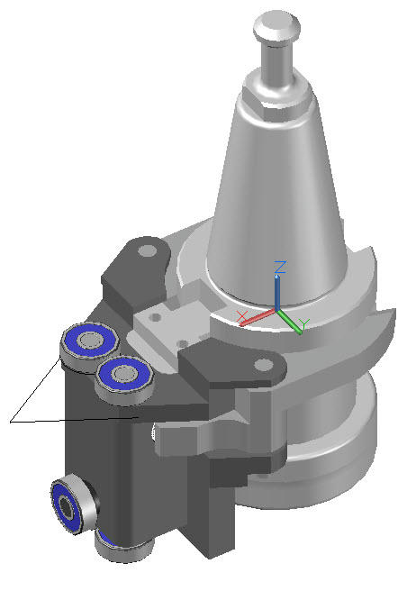
Tool Gripper:
Results 1 to 8 of 8
-
01-17-2012, 01:41 PM #1
 Junior Member
- Join Date
- May 2007
- Posts
- 68
Epoxy Concrete CNC mill 700x500x400 Design and Build
-
01-18-2012, 04:30 PM #2
Registered
- Join Date
- May 2010
- Posts
- 307
Looking forward to seeing your pour, John!
-
01-22-2012, 09:49 PM #3
Registered
- Join Date
- Nov 2011
- Posts
- 0
John good to see you gong forward with this ambitious project, I wish you luck!
-
01-23-2012, 09:00 AM #4
Gold Member
- Join Date
- Jun 2006
- Posts
- 2512
In the isometric views the horizontal axis drive belt arrangement overhangs the end of the mounting base. In the plan and front elevations it is in front of the mounting base?
Phil
-
01-24-2012, 12:17 AM #5
Registered
- Join Date
- Nov 2011
- Posts
- 0
If you look closely at the isometric view it appears to overhang however if you look closely at the right front view photo, you can see that there is a pocket cut in the structure to provide belt clearance. The edges do not have dark lines so it can be hard to see them, but look closely and there is a deep pocket cut into the structure, which makes the drive belt LOOK like it overhangs. Originally Posted by philbur

-
01-24-2012, 12:42 AM #6
Gold Member
- Join Date
- Jun 2006
- Posts
- 2512
Yes, now I see it, I think.
Phil
Originally Posted by sburck
-
01-24-2012, 01:12 AM #7
Member
- Join Date
- Sep 2005
- Posts
- 1195
Hi John,
You will have 2 drive on Z axis? I did not see the ballscrew, only linear slide.
-
01-25-2012, 07:34 PM #8
Registered
- Join Date
- Aug 2008
- Posts
- 1166
It looks like in the top view there's a single screw for the z axis in the center of the bridge, behind the y axis along with more linear bearings.
CNC mill build thread: http://www.cnczone.com/forums/vertical_mill_lathe_project_log/110305-gantry_mill.html


 Reply With Quote
Similar Threads
-
Epoxy Granite In Practice (Mineral Casting, Polymer Concrete)
By johnohara in forum Epoxy GraniteReplies: 71Last Post: 08-25-2020, 01:18 PM -
Epoxy-Granite CNC Lathe Design (and Build)
By romihs in forum Vertical Mill, Lathe Project LogReplies: 8Last Post: 02-16-2016, 06:07 PM -
Epoxy Concrete Commercially Made Machines only
By JohnMcNamara in forum Epoxy GraniteReplies: 5Last Post: 05-31-2011, 03:05 PM -
Epoxy Concrete Aggregate Ratio Mixing Method
By JohnMcNamara in forum Epoxy GraniteReplies: 6Last Post: 05-12-2011, 01:52 PM -
Epoxy concrete CNC mill 500 X 500 X 320h work area concept drawings
By JohnMcNamara in forum Epoxy GraniteReplies: 10Last Post: 04-30-2011, 07:09 AM
