


Nope. Still a limiting factor. In my experience anyway...Originally Posted by shred

Results 21 to 40 of 46
-
03-06-2013, 03:19 AM #21dbrija Guest
-
03-06-2013, 03:25 AM #22anglin GuestI actually got the strainer from Walmart. It was more money than I cared to pay for a strainer, but it had the finest mesh size of any I had seen. It originally had a handle on it which I cut off. It's proved to be very handy as a lot of chips make it down into the strainer. It's fantastically easy to clean. Originally Posted by MFchief
-
03-06-2013, 07:51 PM #23GJeff Guest
You'll be clearing some chips with that. Is there any real negative to having some air mix with the coolant as long as you're not creating a froth that doesn't get out of control and eat up your liquid volume?
-
03-06-2013, 08:06 PM #24MFchief Guest
Thanks Anglin, I'm off to Walmart, if it doesn't snow today!
Terry
-
03-08-2013, 06:16 AM #25
 Registered
- Join Date
- Dec 2004
- Posts
- 57
When the pump starts getting a little air when the reservoir gets low, the flow volume is dramatically reduced (about 1/3 normal flow) and the coolant comes out white, rather than aqua green, from all the air mixed in it. Originally Posted by GJeff
No problem! It doesn't have to be a specific store/brand; just a small mesh size. This strainer easily contains the thinner chips from the roughing end mill, which is about the maximum I expect from it. Originally Posted by MFchief
-
03-09-2013, 02:08 PM #26
Gold Member
- Join Date
- Sep 2012
- Posts
- 1543
Lots of cool coolant mods on Andrew G's (Tormach) Google+ page too
-
03-09-2013, 05:10 PM #27
Registered
- Join Date
- Dec 2004
- Posts
- 57
IMO, there should be a summary thread that includes links to all of the enclosure builds and coolant system upgrades. It wouldn't necessarily be a place where people post their mods; those would still be in their own threads. It would be a quick reference guide so people don't have to search for it over and over. Originally Posted by BAMCNC.COM
-
03-09-2013, 09:18 PM #28
Registered
- Join Date
- Jul 2007
- Posts
- 131
That's a nice setup!!!.
Now that you have lived with it a few months is it working out OK? May I ask a few questions.
Does your coolant tray leak along the welds? Mine leaks pretty bad even with the stock coolant system.
I wonder about the long term health of the lower spindle bearing? The bearing is not sealed and I see in one of your picture a large splash of coolant going right up into the bearing. Maybe thats what happened to nitewatchman's spindle bearing?
During heavy roughing, I have had chips be so hot they melt to the plastic defector I use. Has this been a problem with your setup?
BarryTormach PCNC1100, Mach 3 R3.043.037, MastercamX5 level 3.
-
03-10-2013, 05:53 AM #29
Registered
- Join Date
- Dec 2004
- Posts
- 57
I threw together a quick video showing the clogged coolant drain screen to show the degree to which this can be a problem. Originally Posted by dbrija
Tormach PCNC 1100 - Clogged Chip Tray - YouTube
-
03-10-2013, 06:05 AM #30
Registered
- Join Date
- Dec 2004
- Posts
- 57
Barry, Originally Posted by btu44
Thanks for the compliment! I machine as a hobby, so I'm not running the machine as much as I'd like. I probably only have 10 hours on the new coolant system, so I haven't worked out all the bugs yet.
I never noticed any leaks with the OEM coolant system. The only time I see coolant leaking is when the table starts to fill up from a clogged chip screen. I did a thorough cleaning of the table a few nights ago and notice that the silicone caulk was coming loose near where I saw a small dribble of coolant recently. I haven't seen anything coming down through any other part of the table, though. With the coolant contained in the enclosure, it's not unusual for the floor to be completely dry around the mill when I'm done machining. That's certainly an improvement from before. However, I am cautious, and I've got the machine controller outside of the stand and protected in a work station I built.
I'm hoping that the speed of the spindle will help protect the bearing from any splashing coolant. Perhaps not. I could always build a shield for it.
I haven't had any trouble with hot chips causing damage. My trouble has been from the chip build up on the Y-axis bellows. I'll be replacing the damaged bellows soon and putting an apron over them to prevent damage from occurring again.
-
04-14-2013, 05:34 AM #31
Registered
- Join Date
- Dec 2004
- Posts
- 57
Scaling the values like this worked very well I completed the test of three 1/2" Loc-Line hoses with straight nozzles this evening. The average flow rate over nine samples was 505 GPH. With straight nozzles on the ends of the hoses instead of 90° nozzles, the flow stream is much smoother. I've attached a picture for comparison. There will be video later, as well. Originally Posted by anglin
My system with 1/4 hp pump and PVC manifold:
Three 1/4" hoses, 90° tip: 293.1 GPH
One 1/4" hose, 90° tip: 115.1 GPH
One 1/4" hose, straight tip: 127.1 GPH
One 1/2" hose, straight tip: 239.6 GPH
One 1/2" hose, straight tip plus two 1/4" hoses with 90° tip: 369 GPH
Three 1/2" hoses, straight tip: 505.1 GPH
I measured my garden hose last summer and it took 18 seconds to put two gallons in a bucket. I was putting two gallons in a bucket in 14 seconds with the coolant system. It's worth mentioning that my return system is thoroughly overwhelmed by this amount of coolant. Practically, I'll have to add another coolant return from the tray under the chip screen in the Tormach stand or else this amount of flow is totally unusable.Christopher Anglin
www.mc2racing.com
-
04-14-2013, 12:44 PM #32
Registered
- Join Date
- Jul 2006
- Posts
- 367
Hello Christopher, Although not a Tormach, I basically converted my mill's coolant system, in the same way as you have. I also had issues with the the amount of coolant overwhelming the original drain system. Here's a couple things I did .........
I eliminated any type of screening/chip catching in the pan area and moved that function externally. Basically, let the chips flow out with the coolant.
Here's a pic of my tank... (don't laugh, my grandkids out grew the toy box and I just repurposed it)
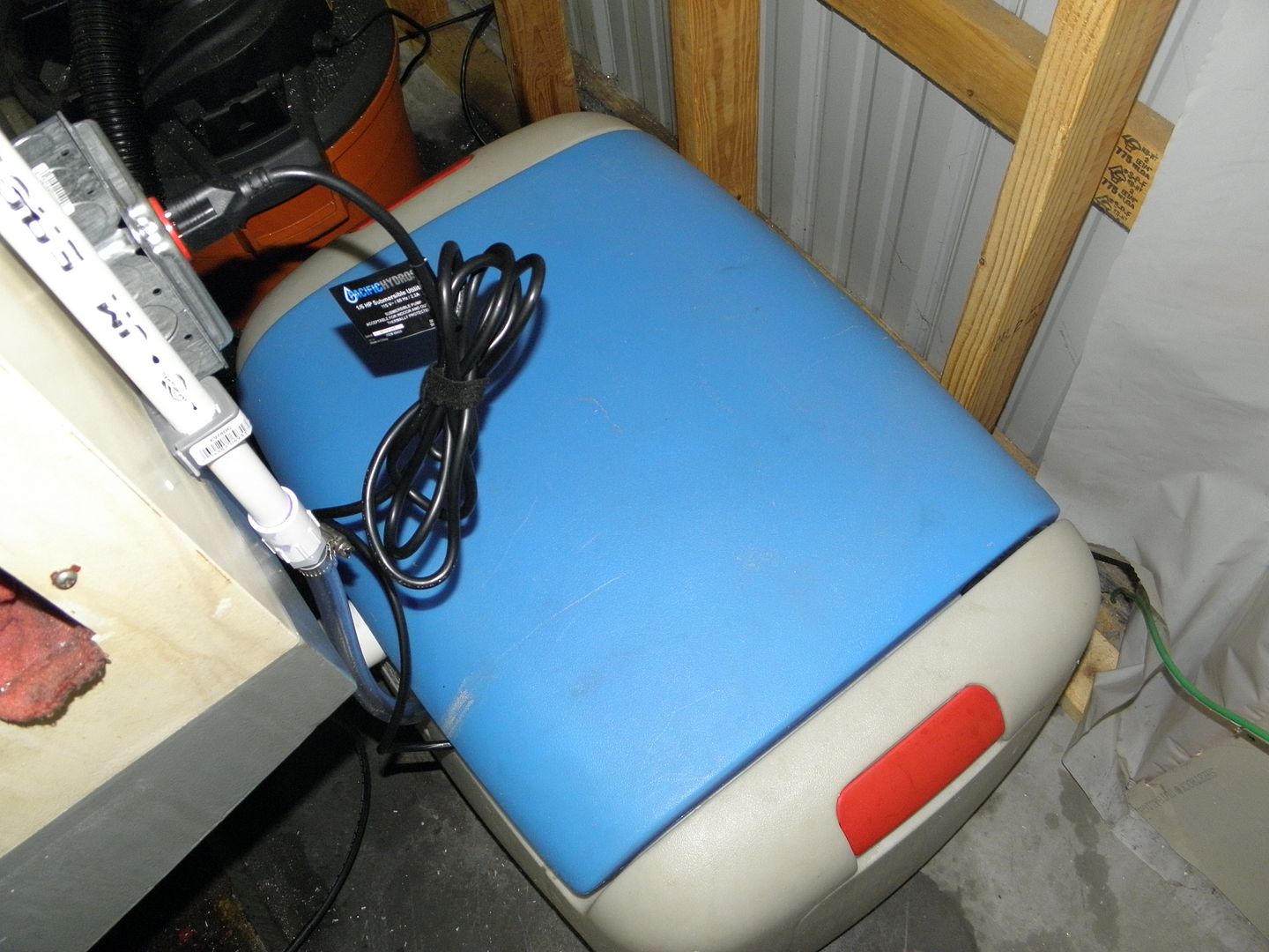
I also repurposed the original coolant tank. It acts as my chip collector/strainer. Here is a shot of the original tank inside the toy box (with 20 gallons of coolant). I'm probably going to drill some holes in the original tank to facilitate the overflow. I just didn't do it yet, till I have seen how the system works.
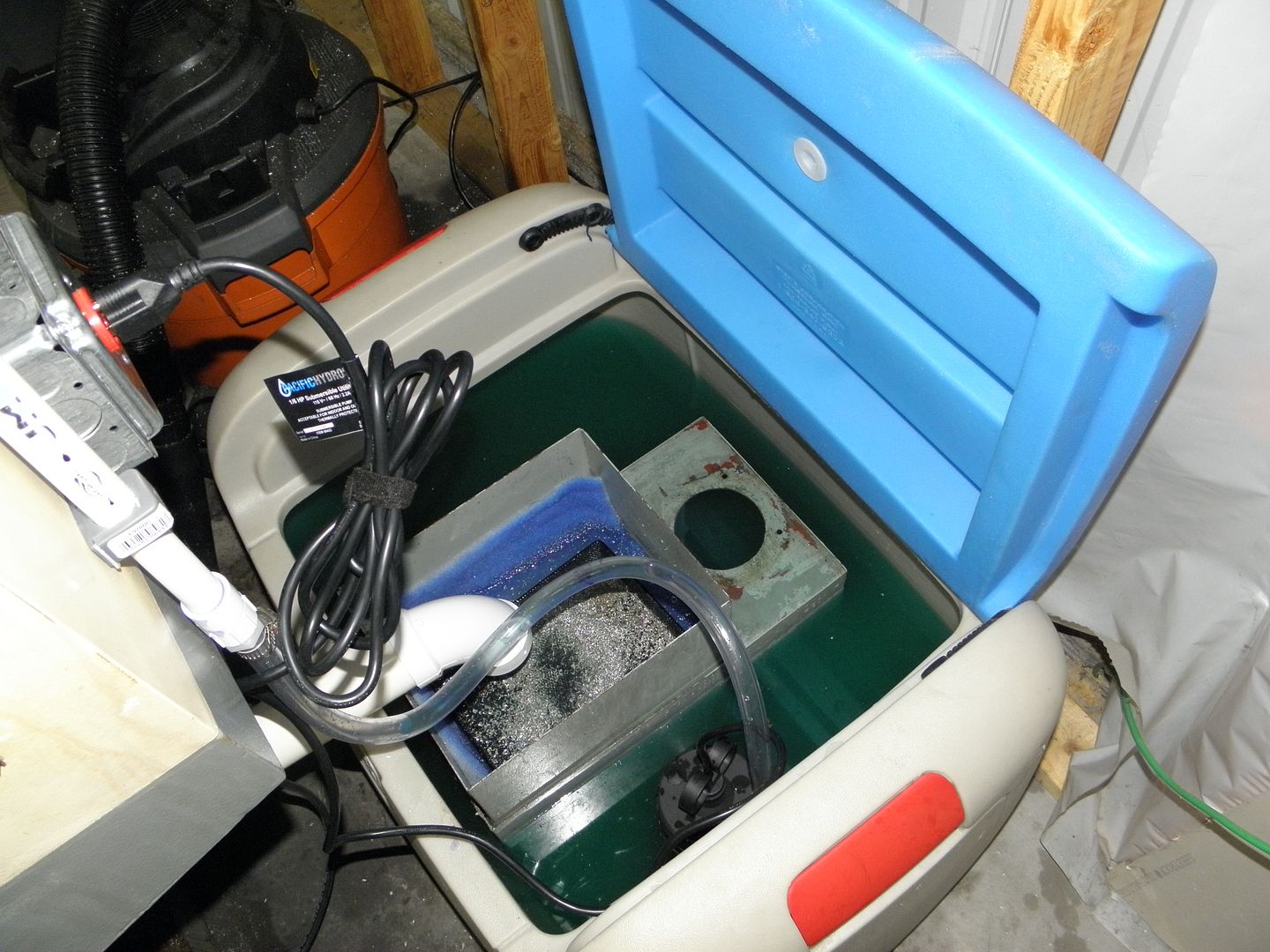
I found that cleaning out the chips is so much easier this way.
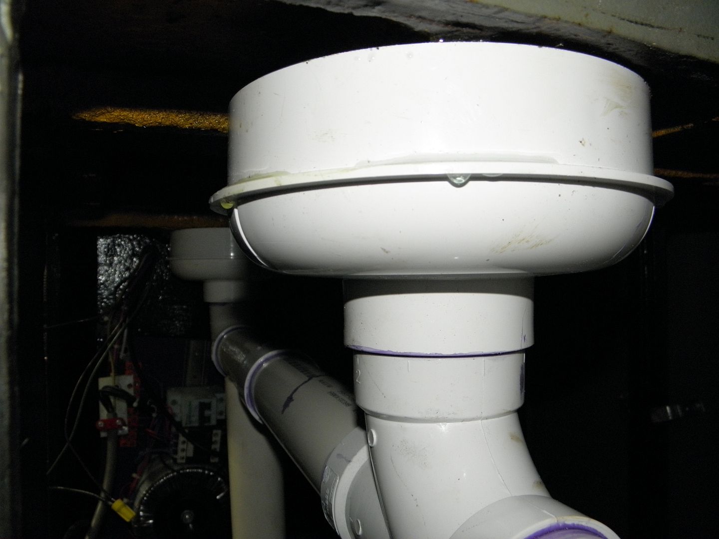
In my situation, I also installed a second drain opposite to the old one. now I have drains on the left and right sides of the mill.
Lastly, since you installed a nice pump, you may want to install one of these to help clean the machine....
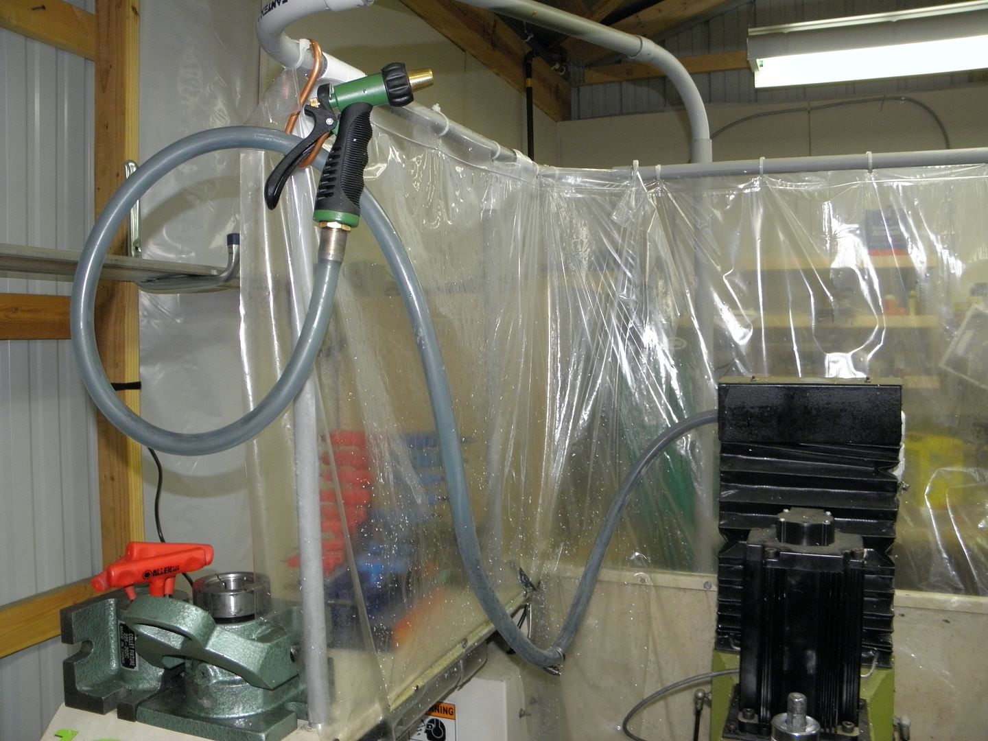
So much better than using air
pete
-
04-14-2013, 10:37 PM #33
Registered
- Join Date
- Dec 2004
- Posts
- 57
That looks like a fantastic idea for a coolant return upgrade which I may have to incorporate. Here's what the coolant system looks like now. Originally Posted by slowtwitch
Tormach PCNC 1100 - Further Flood Coolant System Upgrades, Maximizing Flow - YouTube
Skip to 4:30 to see the flow going into the enclosure.Christopher Anglin
www.mc2racing.com
-
04-15-2013, 12:37 AM #34
Registered
- Join Date
- Mar 2013
- Posts
- 91
You must have tried pretty hard to clog the stock 3"x 9" Tormach drain. I have yet to clog the stock tormach 3"x 9" drain with the new 1200 GPH pump.
Don Clement
-
04-15-2013, 12:57 AM #35
Member
- Join Date
- Jun 2005
- Posts
- 656
FWIW, my old and tired drain basket clogs quite quickly now with the stock pump and lots of aluminum removal. Replacing the screen helps but doesn't entirely solve the problem.
-
04-15-2013, 02:26 AM #36
Registered
- Join Date
- Dec 2004
- Posts
- 57
Not really. When it is backing up like that it happens when the basket is filled to the top. It clogs about every third one of these: Originally Posted by takewhatyoulike
Tormach PCNC 1100 - Coilover Suspension Spring Perch Manufacture - YouTube
I think shred's post pointed out the issue. Even when I scoop out the screen, it doesn't get clean because there is so much chip debris stuck in the screen.Christopher Anglin
www.mc2racing.com
-
04-30-2013, 05:25 AM #37
Registered
- Join Date
- Dec 2004
- Posts
- 57
I've completed the neoprene chip guards over all of the axis bellows; Z-axis, Y-axis front and Y-axis rear. I even put a bonus guard underneath the head to prevent chips and coolant from going into the cast hole in the bottom of the head.
Tormach PCNC 1100 - Neoprene Chip Guards (Darth Vader Conversion) - YouTube
I know the video is long, but I detailed the design completely. My recommendation is to purchase the Tormach Y-axis rear cover if you are using the chip guard that mounts to the table. The Z-axis appears to be more functional for convenience when it's time to clean up. With my table-mounted chip guard removed (because of the full enclosure) I was starting to get excessive chip build up on the front Y-axis bellows which was causing damage to the bellows structure, which is exactly what these chips guards prevent. The Tormach solution is quick and easy but may not meet all of your requirements.
All four pieces were cut from a 36" x 30" piece of 60 mil neoprene. I had the concept before I started, but I wasn't certain about the execution and in fact I slightly changed direction midstream. The work turned out very well. It's been used during dry cutting recently but I haven't done anything with coolant yet. I'll certainly get video of it when the coolant is flowing on my next part.
Here's the chip guard in action during Tormach TTS SuperFly fly cutter testing:
Tormach PCNC 1100 - TTS SuperFly Fly Cutter Testing - YouTubeChristopher Anglin
www.mc2racing.com
-
04-30-2013, 10:39 AM #38
Banned
- Join Date
- Jun 2012
- Posts
- 111
Now that I have my coolant system upgraded, I am also having problems with the chips clogging the chip tray. I may have to add a 2nd drain on the RS of the machine. Is anyone working on a chip auger for the Tormach?
-
06-05-2013, 04:45 AM #39
Registered
- Join Date
- Dec 2004
- Posts
- 57
I had the coolant tray under the table overflow recently when I was out of the garage for a few minutes. It's been running for several months without any trouble, so I suspected a clog but didn't find one. Testing indicated the coolant system flow had increased over the flow rate when I originally installed the system. Apparently that extra flow was just enough to cause trouble. So, it was time to install a second drain. I completed that this afternoon in about an hour. Here's the video:
Tormach PCNC 1100 - Coolant Mod, Adding a High Flow Drain - YouTube
The system now has no trouble handling the 500 GPH flood coolant setup if I decide to run that configuration.Christopher Anglin
www.mc2racing.com
-
07-09-2013, 02:31 AM #40
Registered
- Join Date
- Dec 2004
- Posts
- 57
The Loc-Line circular flow nozzle kit is the last planned mod/test I have for the coolant system upgrade. I wasn't convinced that I'd like this one, but it seemed like an attractive mod when I first considered it. Given the significant volume I can move out of both the 1/4" and the 1/2" Loc-Line with the 1/4" nozzles (three hoses), I figured this one wouldn't provide much benefit or additional gain. I've attached pictures to this post, but there's probably a video in the future. Here's the summary:
I purchased a 1/2" Loc-Line Circular Flow Nozzle Assembly (McMaster PN 10095K72), which includes 15 nozzle segments and a cap. You'll have to get the male threaded connector to attach it to something. The nozzles each have 9/64" orifices. The flow pressure with my system seemed very low and the flow velocity calculation shows this as well. It flowed much more volume than it looked like it was flowing. Here's the flow results:
- average flow over five tests: 404 GPH
- average flow velocity: 9.3 ft/s (compared to 26 ft/s for the single 1/2" hose, 1/4" nozzle)
Here's the result compared to the other tests I've conducted:
My system with 1/4 hp pump and PVC manifold:
Three 1/4" hoses, 90° tip: 293.1 GPH
One 1/4" hose, 90° tip: 115.1 GPH
One 1/4" hose, straight tip: 127.1 GPH
One 1/2" hose, straight tip: 239.6 GPH
One 1/2" hose, straight tip plus two 1/4" hoses with 90° tip: 369 GPH
Three 1/2" hoses, straight tip: 505.1 GPH
One 1/2" hose with 15-nozzle circular flow assembly: 404 GPH
Given the low pressure, I don't think I'd run this system for when I need to clear chips out of pockets. I'd actually prefer my typical setup which is the three 1/4" hoses that flows about 300 GPH. That setup has way more power for removing chips. Take a look at the second picture, particularly. Compared to the three nozzle setup, the flow looks pretty pathetic. I would have never guessed just by looking at it that it was flowing a measured average of more than 400 GPH.Christopher Anglin
www.mc2racing.com

 Reply With Quote


Similar Threads
-
RF45 Clone with full enclosure, coolant, and tool changer
By mikemaat in forum Vertical Mill, Lathe Project LogReplies: 161Last Post: 06-07-2015, 08:50 PM -
new linear way mini millw/full atc, coolant, enclosure etc.
By fixridermtl in forum Vertical Mill, Lathe Project LogReplies: 13Last Post: 06-18-2013, 05:48 PM -
Torus Pro Coolant System And Enclosure Upgrades
By SCzEngrgGroup in forum NovakonReplies: 11Last Post: 04-15-2013, 08:15 PM -
Flood Coolant System Upgrade
By saabaero in forum Tormach Personal CNC MillReplies: 15Last Post: 03-19-2011, 01:10 PM -
Taig Drainage/Coolant System-Enclosure Build~ Pictures~Video~!
By CROSSHATCH in forum Taig Mills / LathesReplies: 25Last Post: 01-16-2008, 12:58 AM
