


Hi,
I'm playing around with a MOSFET H-bridge and IR21844 halfbridge drivers. I'm seeing what I believe are some strange looking gate drive waveform, especially on the high side MOSFET and I'm asking for advice on what might be the cause.
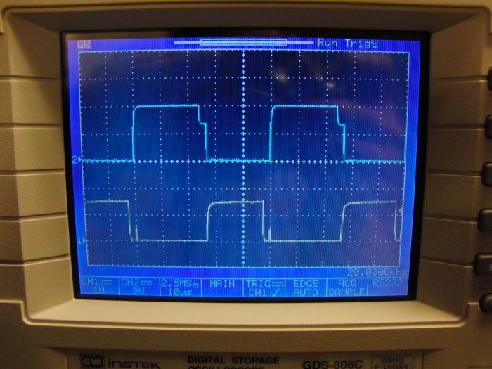
Here's how it looks with no load attached to the bridge:
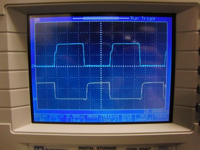
As you can see there's a "bumb" on the falling edge of the gate drive signal and there's also some ringing on the low side drive signal but that goes away when I attach a load to the output:
Here you can see that the "bumb" has moved to the rising edge instead. The scale for the upper trace (high side gate) is 20V/div in both pictures, the bridge voltage is 24V and the logic supply voltage is 15V. The "bumb" is right on the 24V mark which leads to believe it has something to do with the bootstrap circuit. But what, and why does move from the falling to the rising edge depending on if there's a load attached or not?
Here's part of the schematic, the MOSFETs aren't STW75NF20 but rather STW52NK25Z.
Does anyone know of if there's some "generic" cause for this thing and/or do I need to worry about it or is it even "normal behaviour"? Have I choosen the wrong bootstrap diode (ES1J)? Unsuficiant Cboot (470nF) unsufficiant decoupling on the supply, to large RBoot?
TIA
/Henrik.
Results 1 to 4 of 4
-
02-18-2010, 08:32 PM #1
 Registered
- Join Date
- Jul 2007
- Posts
- 887
High side MOSFET gatedrive waveform question.
-
02-19-2010, 09:05 AM #2
Registered
- Join Date
- May 2006
- Posts
- 161
Hi Henrik,
I guess you have uploaded twice the no-load picture as the attachments share the same name.
Anyway I am not sure this bump is a normal condition. The ringing at the low side is also connected to the same source as it is shifted the same time. But you said it is removed when you connect a load.
Do you have a capacitor that bypasses the power line? I've seen quite strange things when there is not. As I look at the waveforms again I think this has something to do with the gate drive, as the bump's bottom is located at exactly the supply voltage - 24V. Maybe you are right to think about the 21844's external components, but I cannot say what to change though.
Todor
-
02-19-2010, 09:48 AM #3
Registered
- Join Date
- Jul 2007
- Posts
- 887
Hi Todor,
From this computer I can't see the photos at all but I'll look into it later, are you saying that the two photos of the scope are the same? I thought I checked that but may have screwed something up when uploading. Anyway...
Yes, there's a 680uF in parallel with 1uF cap on the bridge supply voltage and electrolytic and ceramics bypassing the logic supply close to each driver IC. And yes, the ringing on the the low side disappears when the load is connected.
There's not that many external components to play around with but I don't like to stumble in the dark just trying things without understanding why I'm doing it. That's why I'm hoping someone can give me a hint on what's going on and where I might have messed up.
Thanks!
/Henrik.
EDIT: Yep, I had messed up the links to the photos....sorry about that. Hopefully it's correct now, if not I'll fix it later today.
-
02-19-2010, 01:21 PM #4
Registered
- Join Date
- Jul 2007
- Posts
- 887
Hello again.
It actually looks like this is how it's supposed to look. I've browsed some application notes etc and in the datasheet for the TD340 full bridge driver I found the attached picture illustrating the voltage at the high and low side gate. There's also similar graphs in the Sipex application note ANP20 which also describes more in detail what is happening
This is pretty much exactly what I see on my scope except I get the "bumb" at either turn on or turn off depending on if there's a load attached or not - which is still a bit strange to me. Perhaps I'll get it at at both turn on and turn off once the load is increased to more realistic levels. At the moment I'm driving less than 500mA thru the bridge.
I'm still interested in anyone's opinion though!
Thanks!
/Henrik.


 Reply With Quote
Similar Threads
-
Best MOSFET Driver and MOSFET choice for an H-Bridge Stepper Driver?
By joprinz in forum CNC Machine Related ElectronicsReplies: 4Last Post: 04-28-2011, 09:57 AM -
High side driver
By MechanoMan in forum Open Source Controller BoardsReplies: 12Last Post: 01-11-2009, 07:09 PM -
how do I get a good waveform on my laptop
By cob in forum Machines running Mach SoftwareReplies: 17Last Post: 05-17-2008, 05:19 PM -
HIP4082 - Continuous High Side with Charge Pump
By chostelet in forum CNC Machine Related ElectronicsReplies: 2Last Post: 10-02-2007, 11:46 AM -
H-Bridge high side floating supply
By niclatrique in forum CNC Machine Related ElectronicsReplies: 5Last Post: 10-31-2006, 04:19 AM
