

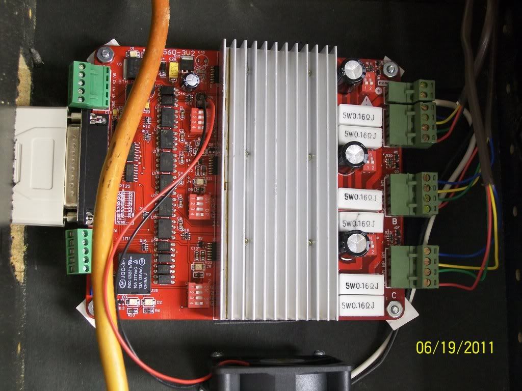
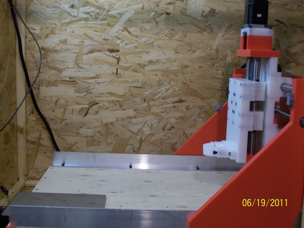
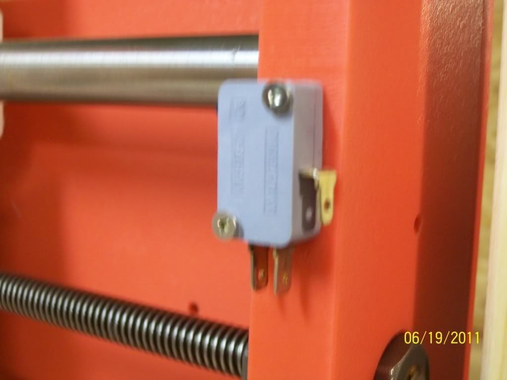
I need help wiring my limit switches on my cnc that I bought on Ebay. I am putting up pictures so that someone can help. There are 6 limit switches (3 are Red and 3 are Gray). There is a limit switch on top and bottom of the Z-Axis, on the right and left side of the X-Axis, front and back of the Y-Axis. My board for the limit switches says CCOM, the next one says L10, L11, L12, L13. If there is any other information that someone may need please ask and I will get you the information. I have looked on the internet and I only find information on 2 wire limit switches and not 3 wire. Any and all help would be greatly appreciated.

Thread: How to wire my limit switches
Results 1 to 16 of 16
-
06-19-2011, 10:58 PM #1
 Registered
- Join Date
- Mar 2011
- Posts
- 0
 How to wire my limit switches
-
06-19-2011, 11:32 PM #2
Member
- Join Date
- Apr 2007
- Posts
- 8082
Three wire switches have a Common (Com) terminal, a Normally Closed (NC) terminal, and a Normally Open (NO) terminal. The Com terminal is the one on the long side, the two that are close together are the NC and NO terminals. Wire the Com and NC, and leave the NO terminal unconnected. Most limit switch wiring schemes use the NC configuration so that a broken or intermittent wire will stop the movement if it opens up.
CarveOneCarveOne
http://www.carveonecncwoodcraft.com
-
06-20-2011, 12:35 AM #3
Gold Member
- Join Date
- Jan 2010
- Posts
- 2141
The next piece of the equation that you need to determine is what pins of the DB-25 connector of your driver board are connected to L10, L11, L12, and L13. You would probably choose one of those pins to use for your limit switches (all of them wired in series). Then you could use the other pins for separate home switches or other purposes. Either you need to check your documentation to determine the mapping of L10 etc. to the DB-25, or else you will need to trace the wiring on the circuit board to determine that.
Once you have that info, then you need to configure Mach3 (if that is the software that you are using) to tell it which pin of the DB-25 will be connected to your limit switches, and whether your limit switches are set up for active high or active low.
-
06-20-2011, 01:32 AM #4
Registered
- Join Date
- Mar 2011
- Posts
- 0
I was wondering if anyone could post a pic to the answers listed below. I am new to wiring them and I would like to make sure that I am doing it right. I would also like to state that I am going to be using MACH 3. Any and all help would be greatly appreciated.
-
06-20-2011, 02:04 AM #5
Registered
- Join Date
- Jan 2005
- Posts
- 398
I hope you got some documentation with your machine. Or at least a sample XML file if you are using Mach 3.
The above answers give you most o what you need but I will try to put the information in a different form.
What the suggestion is that you wire all 6 switches together in one loop. In series. Also do it in a way that if one or more switches is triggered or a wire breaks the controller will take action. To wire them in series you need to wire as follows.(sorry I not able to send a drawing as I am traveling)
Join a wire to L10 to COM on the switch closest to you controller. Then join a wire to the terminal on the same switch marked NC to the common on second switch. Next a wire from NC on that switch to the common on the next one. Continue this pattern till to run out our switches. The final NC terminal is the connected to the common on the controller board.
Then you have to make sure Mach knows where the limit switches are connected etc.
Does this help any?
Doing it this way gives you three other inputs you can use for other things such a touch pad etc.
Another way is to put only two switches in series on each input. This will use three inputs instead of one. There are plus and minuses to hooking them all together. Check the zone for those debates.
I am please to help answering more questions.
Good luck
Dave
-
06-20-2011, 11:11 AM #6
Member
- Join Date
- Apr 2007
- Posts
- 8082
Take a look at Pminmo's site for home and limit switch wiring information including wiring diagrams. There are lots of other articles listed on the right side of this page that may interest you.
CarveOneCarveOne
http://www.carveonecncwoodcraft.com
-
06-20-2011, 11:05 PM #7
Registered
- Join Date
- Mar 2011
- Posts
- 0
Can someone explain to me what the common is? What port would it go into?
-
06-21-2011, 12:54 AM #8
Registered
- Join Date
- Jan 2005
- Posts
- 398
EM
C, common or com are all names for the terminal on a limit switch than can be used with either the NO ( normally open) closes when the lever is pressed or the NC (normally closed) open when the lever is pressed. The link that carve one gave is really good. It should explain what you need to know. If not do you have a friend that knows a little about electronics?
Dave
-
06-21-2011, 02:02 AM #9
Member
- Join Date
- Apr 2007
- Posts
- 8082
Common can mean a lot of things in electronics, but generically speaking it is a common tie point for related circuits. More specifically, it is the return connection back to the power supply.
For a simple 5vdc PSU with two output terminals, +5vdc and -5vdc, the common return connection would be the -5vdc terminal if the circuit being powered are 5v logic devices.
For a PSU with three output terminals, +5Vdc, -5vdc, and a COM terminal, the Com terminal is connected to the PSU chassis and you can use either the +5vdc or the -5vdc as the "output voltage" if you connect either one of them to the Com terminal with a jumper. Then you connect your power wires from your circuit board to the Com terminal and to the terminal that you want to be the "output voltage" going to your circuit board.
Com can also be used in other ways that I won't go into.
In the case of your mechanical limit switches, the switch has to have a minimum of two connections in order to do anything useful. You have an input and an output, and by pressing on the lever the connection from Com to NC (or NO if you wire it that way) is either broken or closed depending on how it is wired. Mechanical switches are bi-directional and it doesn't matter if the wiring is reversed or not. On a breakout board or a G540 there are pins for use with limit switches and a common connection for the other end of the switches to connect to. You need to read the specs for your particular equipment to find out where to connect the limit switch wires.
Optical limit switches are a different animal. If you don't power them correctly they will not work or can be damaged.
CarveOneCarveOne
http://www.carveonecncwoodcraft.com
-
06-21-2011, 02:35 AM #10
Registered
- Join Date
- Mar 2011
- Posts
- 0
thanks for everyone's help. I am not getting it as I am not an eletrician or wiring electronics type of person. I did a drawing to show what it is that I am working with and I put letters where all the wires are. Maybe someone can explain to me how to wire up the limit switches with the drawing I have done. In simple terms (Example: go from comport on the limit port board to A connector on the H1 switch to H2 switch) if someone could explain it like that I might understand better.

-
06-22-2011, 01:42 AM #11
Registered
- Join Date
- Feb 2009
- Posts
- 38
Is a Normally Open or Normally Closed? Need to know so we can draw your lines correctly.
R/Mike Pensinger
Chief Brewer, The River Company Restaurant & Brewery, Inc. Radford, VA
-
06-22-2011, 01:53 AM #12
Registered
- Join Date
- Mar 2011
- Posts
- 0
I was told that it should be normally Open
-
06-23-2011, 04:00 PM #13
Gold Member
- Join Date
- Apr 2005
- Posts
- 1778
The problem with NO is that you can't tell the difference between an open switch and a broken wire. Of course the converse is that with NC, you can't tell the difference between all of the switches closed and a short earlier in the circuit.
I personally prefer NC switches, as they can detect a broken wire as an open switch and I think a broken wire is a more likely occurrence with moving and flexing going on than wearing through the insulation and shorting. YMMV
I have taken to trying to use a single switch per axis and figuring out where to mount it and how to trigger it so that the same switch works for both ends of an axis. I also use my limit switches as home switches.
On your switches my guess is that they are SPDT (single pole double throw), that c is common to both throws, and that one of a or b is NC and the other is NO. Use a VOM to check continuity between (c and a) and (c and b). When you find which pair is NC, then you can push the button and test for continuity between c and the other pole to verify that it is closed on activate (NO).
Alan
-
06-23-2011, 09:46 PM #14
Registered
- Join Date
- Mar 2010
- Posts
- 371
You have a couple of issues here. One is that you have 6 switches and you have 4 inputs. The other is that you don't see how to wire any of the switches.
Taking the first, first. You only really need one input for all 3 axis home and limit. You probably want to leave at least one input available for other things, most importantly, an autozero detector, which lets your mill find the top of your workpiece automagically.
So you could:
a) use one input, all 6 switches are on that input
b) use two inputs, perhaps all 3 home switches on one, all 3 limits on the other
c) use three inputs, one for X home & limit, one for Y home and limit, one for Z home/limit
d) any other combination
There really isn't any good reason to use anything other than a), but plenty of machines use b) or c), and I've seen one with X on one input and Y/Z on another.
Any of these means you are connecting more than one switch to an input.
There are two ways to do this.
One is to wire all the switches in parallel (all the commons together, all the NOs together).
Then you tie the NOs to the input and connect the commons to the com input. Using "Normally Open", if any of the switches are tripped, the input will change from 1 to 0. As acondit says, the problem with this is that wiring faults or switch failures will result in no protection.
The other way is series. Connect a wire from controller common to the first switch common. Connect a wire from the first switch NC to the second switch common. If you chose, say, a), connect the NC of the 2nd switch to the common of the third, etc. Connect the NC of the last switch to the input of the controller. Repeat as needed.
With a Normally Closed switch, if any of the switches is tripped, or any wire breaks, the input will see a 1, but otherwise it will see a 0.
Mach sees these differently: with parallel, the input is high until a switch is tripped, then it goes low. With series, the input is low until a switch is tripped, then it goes high. Low is less than 1/2 volt. High is >3.5V.
You need what is called a "pullup" resistor between the input and either a +5V supply or the motor supply. Many controllers have this built in. If not, get one from Radio Shack or some other electronics parts store. Anything over a couple hundred ohms is fine. Most controllers are okay with the pullup connected to the motor power supply, but some of them won't allow the input to be more than 5V.
-
10-28-2011, 04:56 AM #15
Registered
- Join Date
- Oct 2010
- Posts
- 317
Just trying to learn here but for homing axis, wouldnt each one need its own input so it knows when to turn each stepper/servo off? If you wired them all the same input then Mach3 wouldnt know until all three have tripped and just thinking here...wouldnt the steppers/servos continue to drive until all three have tripped? Ive never used Mach3 so I dont know how you do would this.
I think you need each home to its own input so Mach3 can differentiate between the inputs and tell each motor to turn off and then wire all the limits in a series in NC fashion so when any of them are hit it shuts it off. Even include an E-Stop in the series with the limit switches or put the limit switches on the E-Stop input so then you would only use 3 inputs(if you have a separate E-Stop input).
On my machine I plan on using 6 mechanical switches for limits and 3 hall sensors for the homing and all limit switches would be in series with the E-Stop using a G540 driver. This would leave me another input to control the outputs I guess...still need to get Mach3 and figure it out.
-
10-28-2011, 04:05 PM #16
Community Moderator
- Join Date
- Dec 2003
- Posts
- 24260
The method that can be used on Mach to save on inputs is to series up the home limits all N.C., the theory behind it is if you home one axis at a time, then only that particular axis will move until its particular home limit is opened, each axis is homed in turn this way. Originally Posted by tjb1

Then after this if any switch opens in normal operation it is considered an axis has over traveled.
Al.CNC, Mechatronics Integration and Custom Machine Design
“Logic will get you from A to B. Imagination will take you everywhere.”
Albert E.

 Reply With Quote
Similar Threads
-
How did you wire your Mesa 7i37 Limit Switches??
By torinwalker in forum LinuxCNC (formerly EMC2)Replies: 2Last Post: 03-08-2011, 02:20 AM -
How to wire E-Stop Buttons and Limit Switches which Pin in Printer Port
By guy2b1 in forum CNC Machine Related ElectronicsReplies: 7Last Post: 06-09-2009, 01:36 PM -
How to wire three limit switches
By bgolash in forum CNC Machine Related ElectronicsReplies: 1Last Post: 02-16-2006, 07:38 PM -
The relationship of limit switches to home switches.
By MikeAber in forum CNC Machine Related ElectronicsReplies: 4Last Post: 11-04-2004, 08:28 PM -
Home switches and limit switches.
By ynneb in forum CNC Machine Related ElectronicsReplies: 5Last Post: 04-08-2004, 11:32 PM
