

well.. it's just that i'm lazy sometimes, but i don't want everyone to know..that's why i come up with solutions like this..
Results 61 to 80 of 438
-
02-06-2007, 09:55 PM #61
 Member
- Join Date
- Jan 2007
- Posts
- 356
-
02-12-2007, 08:58 PM #62
Member
- Join Date
- Jan 2007
- Posts
- 356
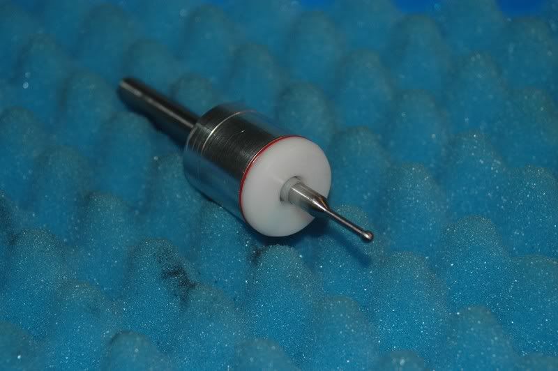
Today, i fiddled around with my touchprobe...
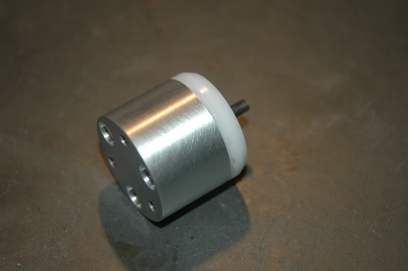
Aluminium housing, milled and cut off
Probe mount..
ANd finally the top end.. i will mount a disc on top, with a pin to fit in the collet
the disc can then be used to center the probe properly..
-
02-13-2007, 10:22 PM #63
Member
- Join Date
- Jan 2007
- Posts
- 356
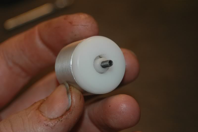
Did some more work on the probe today,
apart from the wiring, the probe is finished
Rear view
Front view
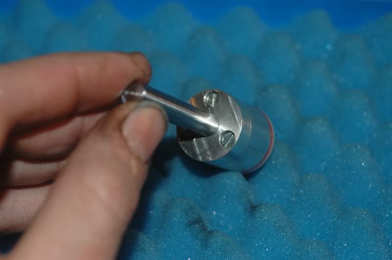
view of the centering screws.. is i loosen them slightly, i can center the probe .
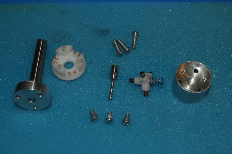
and finally, a handful of parts.. the whole thing is less then 1" in diameter (25 mm to be exact, an inch is 25.4 mm )
-
02-13-2007, 10:34 PM #64
Registered
- Join Date
- Jul 2003
- Posts
- 1766
wow - just wow.
very nice work.
sam
-
02-14-2007, 03:53 PM #65
Community Moderator


- Join Date
- Mar 2004
- Posts
- 1661
This is a beautyful little machine, truly great craftmanship behind it
-
02-14-2007, 07:32 PM #66
Member
- Join Date
- Jan 2007
- Posts
- 356
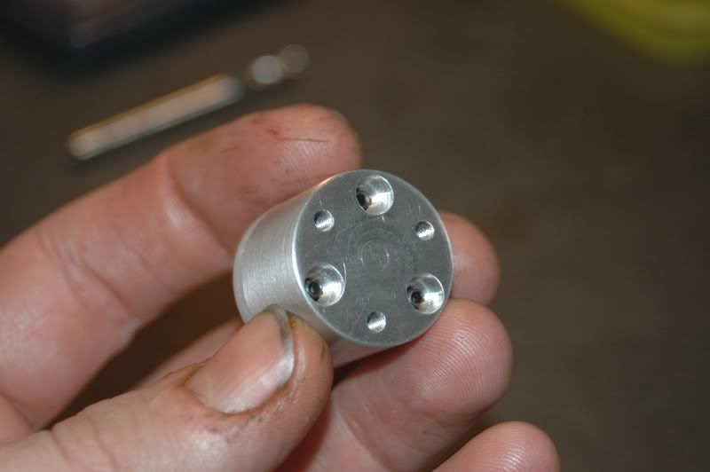
Hold it !!.. wait up!.. i've done another thing today!..
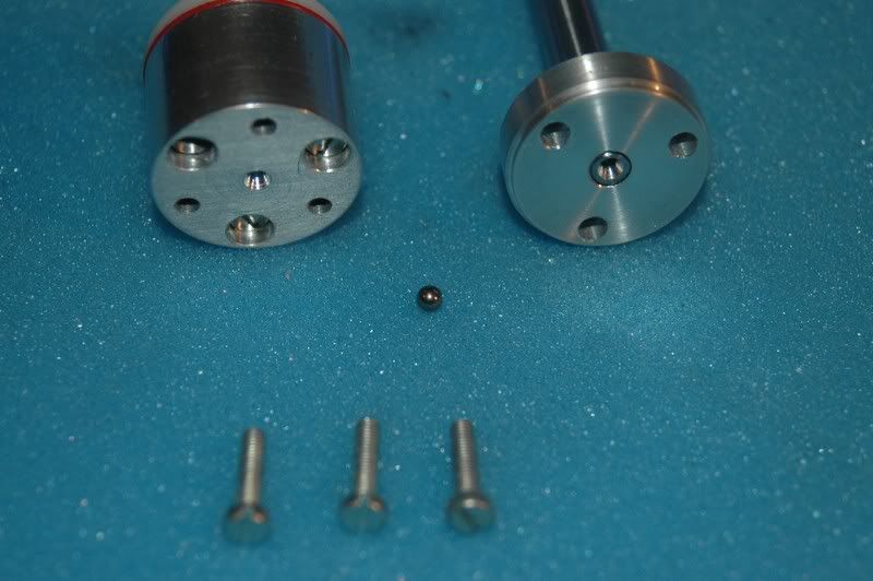
i've drilled small centerholes in both probe body and attach-disc, i can now put a small steel ball in there, and adjust the probe with the 3 screws..
-
02-14-2007, 07:49 PM #67
Registered
- Join Date
- Aug 2006
- Posts
- 74
Very nice the probe Arie.
(Why buy one when you can build one) should be your signature.
-
02-14-2007, 10:14 PM #68
Registered
- Join Date
- May 2005
- Posts
- 674
Come on, man. That's a horrible comparison. An X3 is an absolute piece of junk compared this machine. (nuts) Originally Posted by Brunow

-
02-14-2007, 10:20 PM #69
Registered
- Join Date
- May 2005
- Posts
- 674
Hey arie, awesome progress.
One question, sorry to backtrack a bit. How did you manage to get such a nice surface finish on all the steel plates? Did you surface grind EVERYTHING?
E.g., the assembly below...
The finish in some of the pockets you cut (underside of the mill table) are also ridiculously smooth. What was your finishing procedure for those? Thanks.
Originally Posted by arie kabaalstra
-
02-14-2007, 10:34 PM #70
Member
- Join Date
- Jan 2007
- Posts
- 356
isn't that what i said earlier in this topic?..
this evening i dusted down my trusty ol' Proxxon ( even less than an X3.. it's manually operated, but it's an accurate piece of equipment )
X3?.. if the X3 is the "Sieg X3 mill" then i'd say.. "That's not a CNC mill, that's a conventional machine with a retrofit, still a drill press with cross slides, and the x-axisguide is just too short.. " But it's an affordable machine, which mine isn't by definition.. if i'd have to build them commercially, boy would it cost'ya
what did i do with my little old hobby mill?.. well.. to put it short.. what's a probe, if it doesn't "sense" anything?.. correct.. a nice piece of "nutt'n" so... i installed the "nerve system..
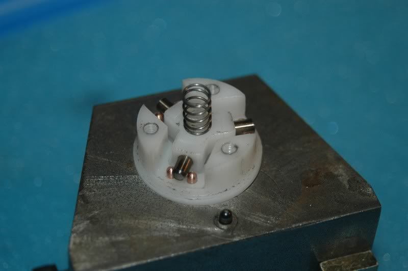
these are the contact pins ( made of Berryllium Copper which is much harder than normal copper )
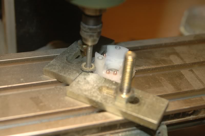
then i fired up my Proxxon, to make some room for the electric wires
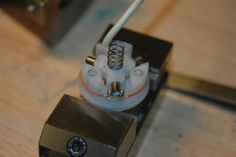
Then.. a very precise job.. soldering the wires, and trying not to melt the delrin body.. the lead to the CNC control used to be a microphone cable ( coaxial ), nice and supple...
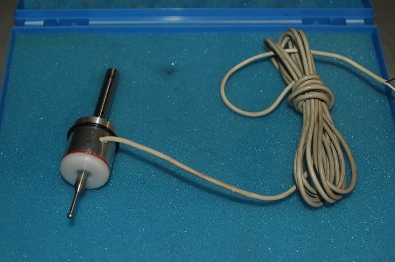
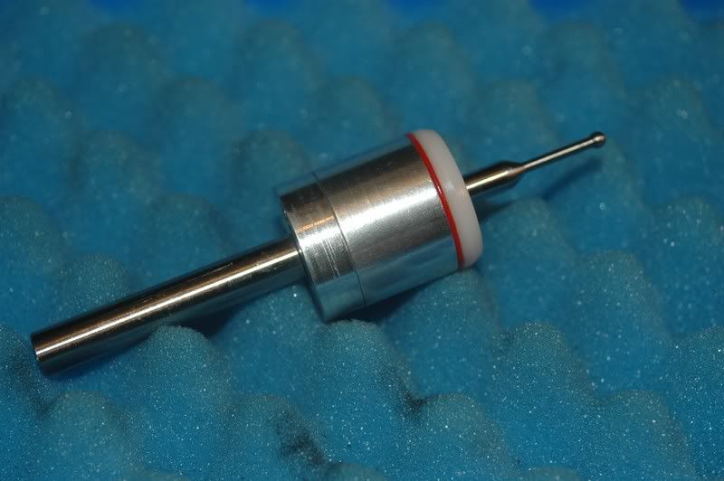
Leading all to: The End result.. a nice little Probe, i've already tested it, Hooked up my Fluke, and as soon as anything touches the probe, it switches
( by the way.. Zumba.. Go easy on Brunow, i know him from the Dutch CNCzone ( www.cnczone.nl ) were i also have a topic on this little machine..:withstupi )
-
02-14-2007, 10:45 PM #71
Member
- Join Date
- Jan 2007
- Posts
- 356
@ Zumba:
Yup.. i Surface ground every part.. Why?.. can't help it.. i'm a professional tool maker..
Cold rolled steel is generally considered "accurate" in dimension.. if you don't have the means of measuring ( Granite table, surface grinder ) you'll never find out if it's bent, warped, or otherwise distorted.. distortion of standard cold rolled steel is generally within 0.1 mm, that doesn't sound like an awful lot, but to me it is... ( made a slide assembly with only 0.005 mm clearing last year )
so.. i have a basic rule : First, deburr, then check for distortion, then grind, to make all sides perfectly parallel ( within 0.005 mm ) then mill, drill wire erode or whatever means of machining i need to do..
i don't take accuracy of materials or machines for granted.. that's the main difference between a "normal steel worker" which is an expert already, and a toolmaker, toolmakers just take one step beyond..
the bottom of the pockets in the mill table, is ground, that's why it is so shiny, but the sides are milled..( the table is in 2 parts )
milling is done whith Carbide endmills with a TiAln Coating, cuttingspeed 300m/min, and 800-1200 mm feed but i don't machine everything down to size in one pass.. i leave 0.2 mm material on, and then finish the parts, this way, i know all dimensions are within ± 0.05 mm which is " my basic tolerance "
-
02-15-2007, 01:22 AM #72
Registered
- Join Date
- May 2005
- Posts
- 674
Pretty cool, to say the least. I'm a stickler for details as well. The only reason why I don't surface grind everything is that my grinder is only 6x18.
Curious... do you have any problems with cold rolled steel warping due to internal stress after grinding both faces? Do you normalize the material before grinding? I've been using hot rolled steel for this very reason.
-
02-15-2007, 08:01 AM #73
Registered
- Join Date
- Oct 2005
- Posts
- 162
Hey Arie,
first of all, i am thoroughly enjoying reading your thread, i check for updates every afternoon after work.
Secondly, your probe. is this your own design, or have you pulled one apart and had a good look inside one to see how it all works?On the other hand, You have different fingers.
-
02-15-2007, 08:22 AM #74
Registered
- Join Date
- Dec 2006
- Posts
- 68
Nice little touch probe, how accurate is it? I have a manual one that spins in a chuck and use your eyeballs, i made by joining a ball on the end of a 6mm C45 rod, i can get within 0.02mm most of the time. The big ones we have at work use compressed air to keep two metal contact plates apart, they can repeat to 0.000 all day until one of us bends the probe
-
02-15-2007, 04:51 PM #75
Gold Member
- Join Date
- Jun 2004
- Posts
- 6618
Excellent project here. You do some fanastic work and the Tool Maker in you is quite evident. I have been following along with lots of interest.
I too am making my own mill, but have chosen different materials. It will be of my own design as well.
Your table design has peaked my interest. I am in the process of designing that part now. I finally have all my rails, bearing blocks, ball screws and such together. Got the last rail yesterday from THK.
I started a thread some time ago on mine, but can't seem to locate it now. I will either find it or start another. Thanks a bunch for posting such detail of a fine design and build.
I'll keep my eyes on it for sure.Lee
-
02-15-2007, 11:13 PM #76
Registered
- Join Date
- Nov 2005
- Posts
- 256
If you're still having problems with the handwheel encoder, it sounds as if you may be missing one channel. This would cause a single count up/down as it is rotated.This is what the PC looks like now.. controllers mounted, power and communications connected.. only the handwheel encoder is giving me a Headache.. it doesn't do what it's supposed to.. the axes rock back and forth instead of running smoothly.. anyone, any clue?..
Mike
-
02-15-2007, 11:19 PM #77
Member
- Join Date
- Jan 2007
- Posts
- 356
which would basically mean?.. that the encoder is broken?.. if so.. then i'd have to get a new one... any way of testing?.. i do have a Fluke 179 could i use that to test my handwheel?..
-
02-15-2007, 11:28 PM #78
Registered
- Join Date
- Dec 2004
- Posts
- 1137
You should see pulses on both channel wires. The B channel will lag the A channel by 90 degrees. In this way, the controller know s which way and how fast the encoder is turning. You did not post a photo of yoor encoder so that's just a basic description.
Jay
-
02-15-2007, 11:44 PM #79
Member
- Join Date
- Jan 2007
- Posts
- 356
my encoder has 4 connectors, V+, V-, A and B, how do i connect my Fluke?
-
02-15-2007, 11:49 PM #80
Registered
- Join Date
- Dec 2004
- Posts
- 1137
Connect the black lead (gnd) to V- (assuming that you encoder is 0V to 5V like the ones I use). Then use the Red probe to see if the voltage pulse on and off between 0 and V+ value. Depending on your encoder, you will need to turn the encoder slowly.

 Reply With Quote
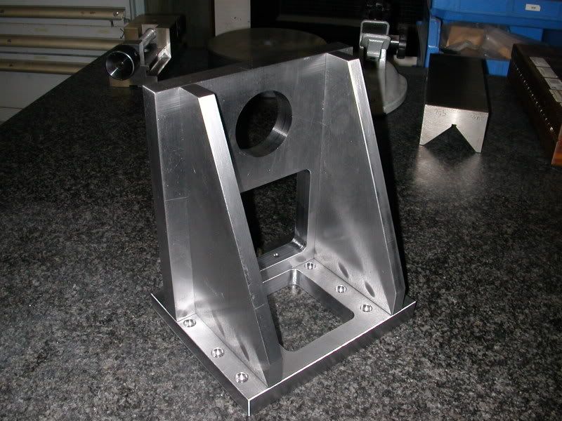
Similar Threads
-
more progress..
By adam_m in forum DIY CNC Router Table MachinesReplies: 0Last Post: 11-26-2013, 03:56 AM -
Design In Progress
By JoeDawg in forum Uncategorised MetalWorking MachinesReplies: 1Last Post: 10-07-2008, 07:48 PM -
My First Router Design & Progress
By watsonstudios in forum CNC Wood Router Project LogReplies: 40Last Post: 07-22-2007, 09:19 AM -
Looking into buidling an Auto-start RPC
By Wendell in forum Phase ConvertersReplies: 2Last Post: 10-12-2006, 03:03 AM -
Alibre design in progress
By xyzcnc in forum Uncategorised CAD DiscussionReplies: 10Last Post: 06-07-2005, 06:49 AM
