


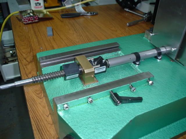
Finished the 3 axis and fully tested.
It's a budget conversion but with pretty good specs.
X axis travel 16", Y axis 8". Z axis around 15"
rolled ball screws on the x and y axis, Stock acme on the z.
Double spring preloaded ballnuts on the x and Y axis, an adjustable backlash nut for the acme z axis.
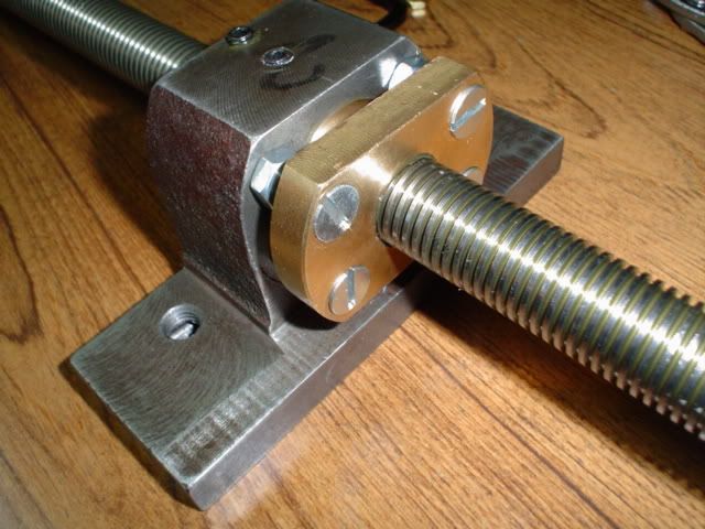
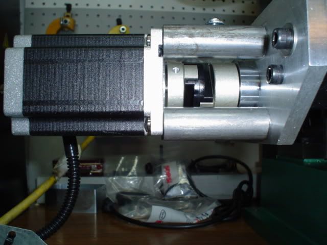
Direct drive with large a Oldham coupling for the x axis. The coupling also serves as the bearing preload nut with a center locking setscrew.
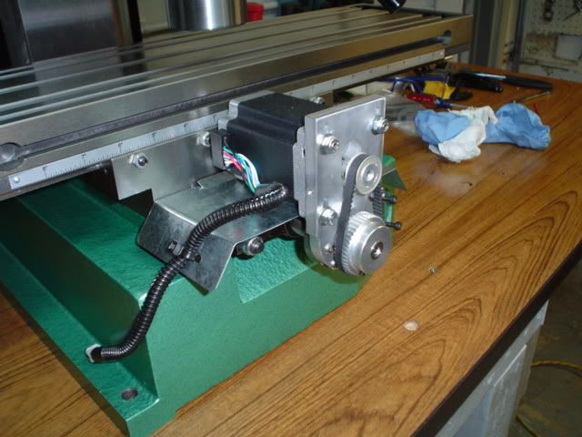
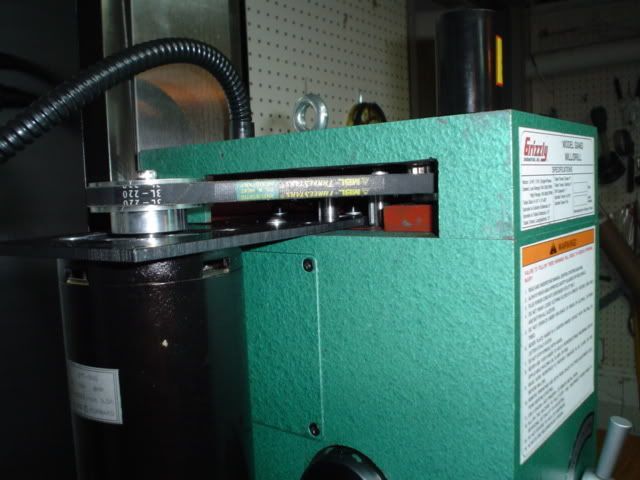
Belt drive y axis using Gt2 3mm pitch pulleys and 6mm belt at a 2-1 reduction. The large pulley also serves as the bearing preload nut with center locking setscrew.
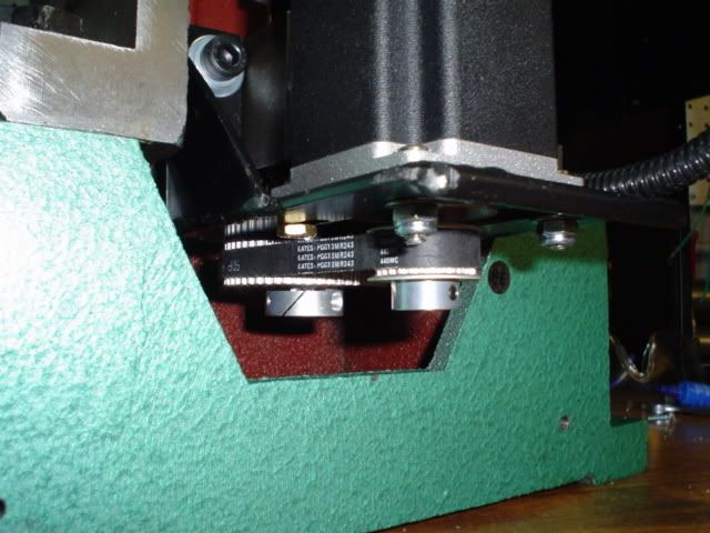
Belt driven z axis with 2-1 reduction gt2 3mm pitch pulleys and 9mm belt
I added a 3rd speed which is a direct to spindle V belt that raises top speed from 2000 to 3400 rpm. It is also very quiet as all gears a bypassed.
It is a 10 minute job to convert back to the factory geared 2 speeds. I added quick knobs to remove the belt/gear top cover to make speed changes faster.
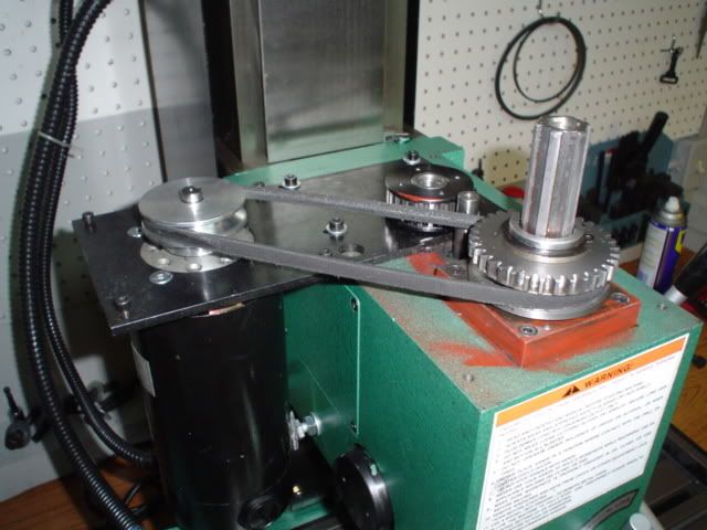
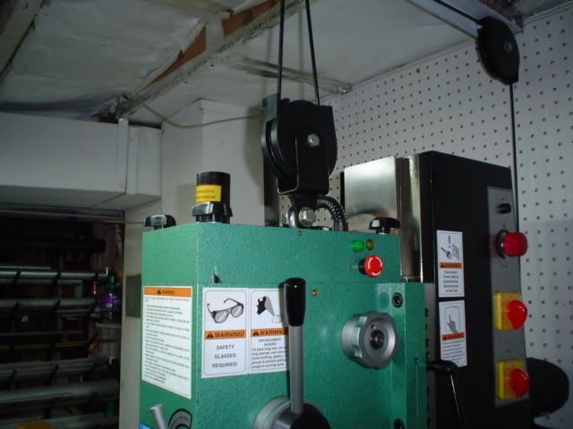
The head is counterweighted with a 2-1 compound pulley. I use 50lbs of which like 100lbs at the head and with the lead screw disconnected I can easily slide the head up and down the column by hand.
I'm using a xylotex drive box with 425 oz steppers. These motors are not exactly speed demons but x and y axis are dead reliable at 75 IPM with tight gibs and bearing preolads. The ACME Z AXIS is limited to 20IPM.
Backlash for the x axis is .0003". I am very happy with the y axis Gt2 belt drive as it is only at .0005" backlash and very close to the driect driven x axis.
The z axis with acme screw is .002" or just under that.
I first tried setting up the motors with my laptop and MACH 3. I thought perhaps I had some big issues with the motors as they were very rough.
I switched to the desktop pc I use for my mini mill and every probelm disappeared.
I still need to add limit switches and finish the 4th rotary axis.
steve
Thread: My X3 conversion.It's alive!
Results 1 to 20 of 35
-
09-25-2006, 01:35 AM #1
 Registered
- Join Date
- Mar 2006
- Posts
- 357
My X3 conversion.It's alive!
-
09-25-2006, 02:08 AM #2
Registered
- Join Date
- Apr 2005
- Posts
- 403
Good Job,
Did you make your own oldham couplers? I would like to see a little detail on your motor set up. I remember seeing it a few days back on one of the other threads along with your preloaded ballnuts. What would really be nice would be an interrupted thread documenting your job.
Good work and can't wait to see some of your projects.
Ron
-
09-25-2006, 02:34 AM #3
Registered
- Join Date
- May 2006
- Posts
- 1469
Hey this looks a great job S_J_H.:cheers:
Can I second Ron about putting a thread together with some detail as reference for interested parties.
Things I would like to know are.
Details about your ballnut preload method.
Same with thrust bearings.
How you managed 8" on your Y.
Did you consider going Nema 34 on the Z and gearing 1 to 1
What microsteps are you running? Was that the difference when you swapped from the laptop?
If not what do you think made the improvement? How stable a pulse train were you getting?
Does the Xylotex buffer the PPT outputs? Were they a bit low on voltage?
I ask these things because I am running off a laptop.
So far testing seems fine but I wonder if when getting serious I will have problems.
Hey sorry for all the questions
-
09-25-2006, 05:18 AM #4
Registered
- Join Date
- Mar 2006
- Posts
- 357
I will go into better detail and answer any questions about the conversion in this thread tomorrow.

Steve
-
09-25-2006, 10:03 PM #5
Registered
- Join Date
- Mar 2006
- Posts
- 357
No, It is SDP 1/2" bore Oldham coupler that has been modified. A 1/4" reducer press fit sleeve was made for the stepper shaft end and a pressed sleeve for the 5/16" threads fitted to the other ballscrew end. The male slot on the ball screw end of the coupler was drilled and tapped for a locking set screw.Did you make your own oldham couplers?
Bearing preload is set by tightening the coupler end with a wrench on the flat and locked in place by the center 5/16 setscrew.
The same technique was used for the Y axis pulley but I just grip the pulley by hand to tighten.


The motors and drive system is by Xylotex. 425 oz steppers in 1/8 step mode.I would like to see a little detail on your motor set up.
It's a 4 axis plug and play system.Not much I can say about it. Just hook em up and go.
Well I bought this mill with the intention to CNC it. However one of my goals was to use as much of the factory hardware as possible to save money.Details about your ballnut preload method.
I used the stock acme blocks as they were doweled and I had a known good "center" to work with which saves a lot of setup and measuring.
I bored the acme blocks out until the external thread diameter of the ball screws was a good tight sliding fit in the block.To determine the center of the blocks which were acme thread, I used a small section of acme thread with a turned tip to indicate off of.
I then tapped the sides of the block for set screws to lock the ball nuts in place needed for locking one nut and machining the dowel slots in the other.
A preloaded double nut needs one nut locked in place and the other able to move fore/aft but not rotate. I noticed the factory setscrews holes that were used in the acme block to adjust for backlash were in a good location to use for a external rotation elimination setup on the Thomson ball nuts.
They could be enlarged for 1/4" dowels and that by a precise mating notch in the ball nut body would stop the nut from rotation but it could still slide in and out. Perfect!
So one nut is mounted in the block and locked in place with the setscrew.
Then placed in the mill and a solid carbide endmill used to plunge cut the holes through the brass block and at the same time cut a matching slot in the hardened ballnut body.
I used stainless dowels loctited into the brass block.A spring is fitted inside the block I found at the hardware store. Once a short section is cut it had just over 100lbs to fully compress. I have read 85lbs preload is about right for a 5/8" screw so it seems to work well. Insert the sliding nut first into the block, then screw the other nut into the block until the spring is fully compressed and then back off slightly. Lock it in place with the set screw and then remove. You'll see the witness marks from the setscrew. I used a carbide endmill to cut a nice dimple for the setscrew to lock the nut to the block.
Steve
-
09-25-2006, 10:20 PM #6
Registered
- Join Date
- Mar 2006
- Posts
- 357
The x axis I used the left side of the table and added a thicker plate and some 7075 round to make a new bearing block.Same with thrust bearings.
The y axis I reused and modified the stock bearing block .
I reused all factory thrusts that came with the mill. But I added deep groove bearings instead of the factory bushed method.
SO my bearings are loaded into the block- grooved race thrust,2 deep grooves,grooved race thrust. Then the thrusts are preloaded slightly to eliminate any endplay and locked in place with the above methods.
The X axis also uses a deep groove at the opposite end.


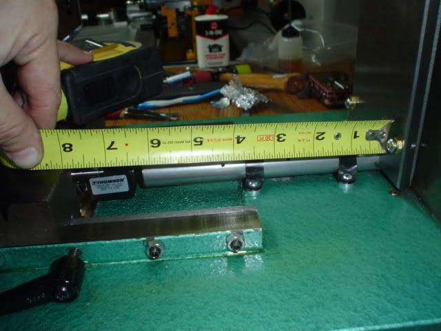
Well quite simple really, a longer screw, spacer blocks( shown in above photo) with larger 3/8" hardened mounting studs, a 1" deep bored hole in the column.How you managed 8" on your Y.
A ballscrew shield with lube holes was added to keep debris off of it.
At the limit of 8" the table does begin to get sloppy as not much dovetail is keeping it in place. But I wanted to max out the y axis travel for the odd job that might need it.

-
09-25-2006, 11:04 PM #7
Registered
- Join Date
- Mar 2006
- Posts
- 357
No, a direct driven stepper that size and power would have kept me from using the xylotex system. I would have gone direct drive on the y axis, but the motor over hang with the spacer blocks used to get 8" travel would have been ridiculous.Did you consider going Nema 34 on the Z and gearing 1 to 1
The Gt2 Pulleys and belts work real well with very low backlash and are probably easier to setup than direct drive and a coupler.
1/8 steps. My laptop is a Dell 2650 a few years old.The driver test showed a decent pulse but with erratic behavior now and then.What microsteps are you running? Was that the difference when you swapped from the laptop?
If not what do you think made the improvement? How stable a pulse train were you getting?
Does the Xylotex buffer the PPT outputs? Were they a bit low on voltage?
I could jog the motors fine one at a time. When I would run 2 or more axis at the same time it just flipped out. The motors just made all sorts of wild screams as they locked up.
I hooked up my desktop and all worked perfectly. I also noticed the motors were smoother running on the desktop.
All I know is MACH has some troubles running on some laptops.
For what ever reason mine can't handle running MACH3.
Steve
-
09-25-2006, 11:13 PM #8
Registered
- Join Date
- Mar 2006
- Posts
- 357
a couple pics of the chip quards for the motors and y axis ways. I may or may not epoxy paint them. The y axis belt shield has a clear lexan cover.


Steve
-
09-26-2006, 12:45 AM #9
Registered
- Join Date
- Apr 2005
- Posts
- 403
Steve,
I went back and reread your post about your motor speed test and your 3 speed system. Very good work!! I like your preloaded ballnuts. Where do you buy your pulleys and belts? Any more details (store and possible part #) on the spring that you used to preload the ballnuts?
For example your main spindle pully, did you cut the v groove in your self, (I believe you said you used an angle of 36 degrees (I only done a little lathe work and I know a threading or other cutters may be 60 degrees, so is the 36 degrees the cutting angle on the cutting tool?) and if so does it just chuck up in a lathe ok or did you have some special way to chuck it up?
Did you build your own Power Supply or just use the 24VDC 5 amp that Zylotex sells? (I didn't know if the 5 amp supply was sufficient)
At 6&1/2 inches of Y travel, is it still pretty tight (as far as the gibs, you mention, it gets a little loose at 8 inches)?
I really like your conversion and I don't want to wear you down with questions. I, my self had been wondering about using a hobbycnc card (it's only unipolar and the 425 in/oz would only yield around 300 in/oz, but it probelly would pay to use the Zylotex in order to get the full rated power from the motor.
I've never seen the X3, so where is the motor in relation to the gear box, and in your 3 speed conversion are you using the stock motor?
What did you do special to get your Z axis down to .002 ( you mentioned an adjustable backlash nut for the acme z axis) if you could detail this a little.
Thanks for sharing your conversion.
Ron
-
09-26-2006, 03:52 AM #10
Registered
- Join Date
- Mar 2006
- Posts
- 357
Ron,
The spring for the ballnut preload I bought at the local Ace hardware store in the spring aisle.
It's OD is about .925", ID is .675", wire diameter about .125" and coil spacing about .250"
I only use a section of less than 2 coils which is somewhere around .375" long if using one of the ground flat ends which is what I did.
I made the spindle and motor pulleys from scratch. They use standard 3/8" V belts which are a 40' included angle but you like to cut them a little less than the belt angle for better wedging/holding power. It's standard lathe work to make pulleys but it depends on how much experience you have with a lathe.
Everybody likes to do things their own way. I use a special tool I made for grooving-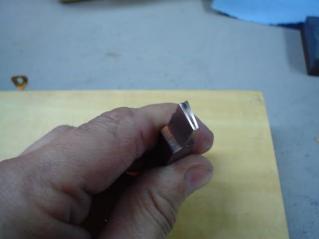
Just a sharp tool that cuts well on the sides and a notched tip to ease plunging and also helps lock the tool into the groove as it cuts.
I set the compound over to 18' and then plunge straight in with the tool using the cross slide to the desired depth. In this case about .385" deep. Then lock the carriage and with the tool still at full depth, slowly and I mean slowly draw the tool out of the groove using the compound.It takes a super wide razor thin chip if done right. It will slice away 1/2 of the pulley groove by the time the tool is retracted fully. Then use the compound again pushing the tool back in and out to clean up the cut once or twice. Rotate the compound to the other direction and again set over at 18' and repeat the process. Measure the width of the groove and widen as needed.
The spindle pulley I made from Iron and is press fit and loctited on.
The motor pulley is aluminum with a key way and the shaft fit is just nice enough to be able to remove by hand.


I used the power supply from Xylotex. I have never had a problem with it on my mini mill but here is a thread on the subject. http://www.cnczone.com/forums/showthread.php?t=21895
The y axis at 6.5" is very rigid. Only way out at 7.5"+ does it get sloppy.Some careful gib adjusting might help.
The GT2 belts and pulleys and couplers I bought from- http://www.sdp-si.com/
The motor is stock and there are pictures above showing it and it's location.
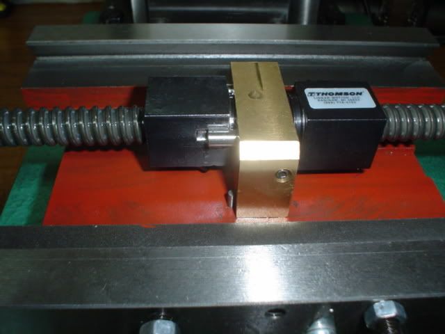
The z axis nut is picture #2 in this thread. I cut the stock nut in 2 parts. The first half(not shown) is set screwed and loctited in place in the iron housing.
The second half is counter sunk for taper head screws. The nut is first screwed into place on the acme thread and then the 4 screws are used to squeeze the nut into the threads(rigid preload) to take up the backlash. I just went by feel and at a nice stiff but not to difficult to turn force the nuts lock it in place.The result .002" backlash. Further preload will lessen backlash but friction is high and so will be wear rate.
I don't think any spring preloaded nut will work to well on the z axis as it will be way to easy to overload any spring tension and defeat the preload but I may be wrong.
Steve
-
09-26-2006, 06:11 PM #11
Registered
- Join Date
- Apr 2005
- Posts
- 403
Steve,
Thanks for the write up. I intend to study this a while. The Z axis stepper is mounted at the bottom of the column using a bracket that appears to be made of steel, any thing tricky about it?
Thanks
Ron
-
09-27-2006, 05:04 AM #12
Registered
- Join Date
- Mar 2006
- Posts
- 357
Ron, the bracket frame is made from 1/8" steel. Rather than spend a lot of time machining the mount, I made a welded steel bracket.The Z axis stepper is mounted at the bottom of the column using a bracket that appears to be made of steel, any thing tricky about it?
Once the motor is bolted to it and the bracket/ frame bolted to the column, it forms a very rigid motor mount.
I'm happy to share my little x3 conversion with others. I got a lot of my ideas from others such as John Stevenson who did a beautiful x3 conversion.
Anyhow, a couple pics of my z axis motor mount.


Steve
-
09-27-2006, 11:03 AM #13
Registered
- Join Date
- May 2006
- Posts
- 1469
Thanks for taking the time to post pics etc Steve.
Hopefully will help inspire more people to get onto this great small mill.:wee:
Wondered how you got 8" without hitting the column but I see you drilled a hole
-
09-27-2006, 02:31 PM #14
Registered
- Join Date
- Apr 2005
- Posts
- 403
I agree with Greolt, a good thread like this should get alot of interest in X3 conversions (It's got mine!!). What is a good vise to use on this size table? In fact, isn't there a site that specializes in the minimills? I don't think I saw John Stevenson's conversion, but if it's anything like yours, it great!!
Anyway thanks for the PICs Steve.
Ron
-
10-12-2006, 10:09 PM #15
Registered
- Join Date
- Mar 2006
- Posts
- 357
Just a update. I finished converting the rotary table 4th axis with a 4 jaw chuck.
I wired standard micro switches for home and limit on the 3 axis.
I adapted my Fogbuster coolant system to the mills head. It is a instant on/off pressure system that produces no fog or mist.Right now I am using a manual air toggle switch but will add a solenoid and have MACH 3 control it.
I made the rotary table bracket using the mill.Circle interpolation and surface finish just smokes my x2 mill. Pretty happy with it so far.
Still to come are a power draw bar, addon high speed spindle and maybe I'll have a go at making a tormach type tool holding system for it.


Steve
-
10-16-2006, 05:05 PM #16
Registered
- Join Date
- Aug 2006
- Posts
- 78
Hello SJH,
Beautiful conversion job, my complimemts. I am interested in this fog buster coolant system and have never saw it for sale. Where can it be purchased. I am sick of breathing all the mist vapor generated by my conventional mist systems.
Thanks,
Dennis
-
10-16-2006, 06:48 PM #17
Registered
- Join Date
- Mar 2006
- Posts
- 357
Thanks Dennis,
http://www.fogbuster.com/frame.htm
I have the 1/2 gallon model which is plenty big. It works as advertised. No mist or fog. Fully Adjustable from air blast only, to a tiny invisible coolant stream or to a full out coolant bath, but never any misting.
I have had it for maybe 2 years and have been very happy with it and use it with any of my machines(mills,lathes,bandsaw) as needed.
It's on the pricy side but it works.
Steve
-
10-17-2006, 01:58 AM #18
Registered
- Join Date
- Aug 2006
- Posts
- 78
Thanks Steve,
I did some research at the web site today and was taken back by the $$$$ price.
With my ongoing health concerns with coolant mist in the shop air, I have been planning to build a similar device for many years. My approach was to use pressure to introduce the fluid rather than a venturi effect thereby avoiding fluid atomization and also the high airflow volume and pressure needed to lift the fluid as with conventional mist systems. Another plan was using a mineature adjustable stroke piston pump activated by a solenoid to introduce coolant in small doses as needed independent of airflow.
I am going to build a device using a household cartridge water filter as a reservoir. By modifying end fittings and adding a regulator and solenoid valve to pressurise it, you can build a similar device for little money. I intend to make a test unit by using a brass block with a needle valve attached to regulate fluid in and soldering a brass tube to it which will mix and direct the output to the work. Pipe it with nylon tubing for fluid and air and I think you have it. Parts cost about $60.00 I will keep you posted. If it works, I will document the plans for others to use.
Dennis
-
10-17-2006, 02:46 AM #19
Registered
- Join Date
- May 2006
- Posts
- 1469
Dennis have you seen posts by Karl on his Fogbuster style build/improvement
http://www.cnczone.com/forums/showthread.php?t=25040
-
10-17-2006, 07:06 AM #20
Registered
- Join Date
- May 2005
- Posts
- 240
You made it sound like it was over a grand. I was thinking I had to see it for myself. Originally Posted by dcprecision
 $310 starting isn't ridiculous but it's not cheap. Looks like it works very well and makes for a simple setup.

 Reply With Quote