


I continued trying to get my PWM to 0~ 10V converter working today and eventually gave up. I can't get any output from the converter and I assume that is why my VSD now won't start now. ( it has to see a 'on' command AND a speed voltage? )
I can detect millivolt changes on the input to the converter ,with my Fluke, so that seems to be working, but as I don't have a CRO I can't prove it.
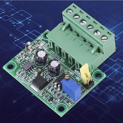
I'm aware the input voltage range can be selected via the yellow jumper. The pot is for calibration of the output.
The vague chinese instructions infer that one can select 0-5V OR 0-10V output but don't say how. There are 2 unused pads on the PCB so I'm wondering if they need to be shorted...dunno. reluctant to short them out in case I do damage.
Has anyone used this particular converter?
In case its a dud, I've ordered another one...and a different one....
Steve
Results 1 to 13 of 13
Threaded View
-
12-16-2017, 10:48 AM #1
 Registered


- Join Date
- Jan 2007
- Posts
- 626
Change BOB PWM signal to 0-10 V signal

 Reply With Quote
Similar Threads
-
convert 5v PWM signal into analog signal ranges from -10 to +10 v
By Hamayel in forum CNC Machine Related ElectronicsReplies: 2Last Post: 12-12-2015, 10:05 AM -
1.6V-3.0V random signal voltage parallel signal from output – Any advice?
By cjchands in forum Mach Software (ArtSoft software)Replies: 0Last Post: 11-12-2009, 11:36 AM -
DR SIGNAL OFF
By mustafaguler in forum FanucReplies: 0Last Post: 02-22-2008, 07:46 AM -
DR SIGNAL OFF
By mustafaguler in forum FanucReplies: 1Last Post: 02-16-2008, 05:26 AM
