


JonOriginally Posted by jonmessenger

low is giving about 5 bars
high is full scale
since found that the 12 volts has nuked the hex inverter!
so need to fit a new one
limping along in open mode for now
cheers
Mike
Results 2,001 to 2,020 of 2415
-
01-12-2013, 03:32 PM #2001
 Registered
- Join Date
- Dec 2010
- Posts
- 0
-
01-15-2013, 06:35 PM #2002
Registered
- Join Date
- Dec 2010
- Posts
- 0
update on my poorly SuperPID
obtained a replacement chip (hex inverter)
removed the old
connected the new
all working fine now - phew!
memo to self 5 volts means 5 volts not 12 volts!
also now have run and speed signals working from my controller
so all in all a very content person!
a few pictures for your delight and amusement
insides (after fitting new inverter)
it's under the LCD so you can't see it
back showing cutouts for the fan (made using my BBox of course!
side showing serious electrical connectors
front
-
01-15-2013, 07:58 PM #2003
Registered
- Join Date
- Oct 2005
- Posts
- 2392
Hi mmcp42, good to hear you got it repaired. Normally I prefer to do a repair like that myself for the customer, because the surface mount IC is not easy to replace.
Obviously you had the skill to change the IC so that saved some delays from international postage.
To the other readers of the thread; mmcp42 and myself had been handling this through tech support emails.
To mmcp42; that's a nice big box with good chunky heatsink and massive fan! I see the fan blows air out the back of the box, but where does the air come into the box? Some holes near the bottom would be optimal as then the cool air flow would be fully past the SuperPID board.
If you worry about dust ingress you can glue or mount a filter over the inlet holes, many commercial devices just use a fine mesh type cloth (like stockings material) glued over the holes on the inside of the box. If you have really fine dust that there are a few different types of foam you can use which will filter well but will need regular cleaning.
-
01-15-2013, 08:17 PM #2004
Registered
- Join Date
- Dec 2010
- Posts
- 0
indeed Originally Posted by RomanLini
excellent support help from Val and Roman
the fan is ex-PC 12 volts (that's what got me into this mess in the first place!)
Val, Roman,
the heatsink was just a chunk of aluminium off eBay
I used some Arctic Ice to ensure good contact
I have several tubes from earlier projects
(usually used when fitting heat sinks to CPUs inside PCs)
slightly larger than necessary, but it's so damned cold in my garage I'm thinking of installing a heater instead of the fan!!!
no ingress air-holes, just general leakage
once I decide where to mount it I will add some inlet holes and a filter
I have a couple of PC fan filters so may well press them into service
I'm just so relieved to have it up and running again
and with all the mains nicely tucked away inside a plastic box
for UK readers the box is from Maplin box MB6
you need the space to fit all the extras like sockets and switches
<= bunny[happy]!
-
01-29-2013, 06:04 AM #2005
Registered
- Join Date
- Nov 2010
- Posts
- 520
Wow this thread is huge! I just read most of it tonight.
I am going to be wiring my SPID soon and want to make double sure I'm doing it correctly. I found this wiring diagram on this thread and want to make sure this is the one to follow.
I will be using the SPID with a G540 and would like the option (using a spdt switch) to manually control the speed with the pot.
Thanks
Rick
-
02-01-2013, 06:00 AM #2006
Registered
- Join Date
- Nov 2007
- Posts
- 277
I'm thinking of getting this. Does this unit generate an ESTOP interrupt if the power output goes too high, or the RPM drops to low? This would be a useful way to detect a machine error.
-
02-01-2013, 08:56 AM #2007
Registered
- Join Date
- Oct 2005
- Posts
- 2392
RicknBeachcrest- Hi, and yes your diagram looks fine.
The switch will select between pot speed control, and G540 speed control from your PC software (ie from mach3).
Guru_florida- Hi. The SuperpID does not generate a separate "error" signal. This has been discussed in the past, and the Super_PID does generate a "TACH" output signal so your controlling software (like Mach3) knows the exact router speed.
From my understanding you could use that to get Mach3 to generate an emergency stop condition.
Regarding the RPM dropping too low, the SuperPID control system actually allows some tolerance of very low RPM and during faults like that will default to a fixed router power level. The idea was to give some tolerance of short term RPM faults like bogging down on a small knot in the wood, or chewing through a clamp etc as in most cases it is better for the router to remain spinning after the fault, and not stop spinning, which can break a tool or bend a collet when the machine keeps moving and the router spindle has stopped spinning.
-
02-01-2013, 04:20 PM #2008
Registered
- Join Date
- Nov 2007
- Posts
- 277
Thanks. The TACH output will do. I use emc2 but I know how to modify the hal to estop on that tach input.
I agree, keep the tool moving - always - if possible. I've jammed a tool before though and at almost full power so estopping at RPM==0 would be good. It would save the machine, and spindle from the stall current. Luckily I was right there at the machine at the time but I am more hands-off now. I am much more experienced so less mistakes, but still I am human and I'll make another one in a matter of time - you can take that to the bank.
Originally Posted by RomanLini
-
02-02-2013, 05:05 AM #2009
Registered
- Join Date
- Nov 2010
- Posts
- 520
Thanks Roman.
I'm good to go now.
Rick
-
02-08-2013, 04:19 AM #2010
Junior Member
- Join Date
- Nov 2011
- Posts
- 107
Hello guys
I just wanted to share my superpid case, i want to say that this product is awesome, it has been running for 7 months and i havent had any problem yet, runs very nice! a very good product.
I made my case with the one that the superpid team sells, its very simple, i have just made some vent holes in the upper corner, sides and rear corner. I made a copper heatsink to make it cooler.
Enjoy the pictures!
-
02-08-2013, 07:04 AM #2011
Registered
- Join Date
- Jul 2009
- Posts
- 690
I said it in your build log and I say it again: that's an amazing build you have there!. I'm pretty sure yout SPID will keep going strong for many years.
That box slightly reminds me of some DLink routers
 http://www.build.cl
-
02-08-2013, 07:14 AM #2012
Junior Member
- Join Date
- Nov 2011
- Posts
- 107
Re: Super-PID new low-cost router speed controller
Yeahh you are right! I should have added more vent holes Originally Posted by Walky
") thanks for your comments!
thanks for your comments!
Enviado desde mi Transformer Prime TF201 usando Tapatalk 2
-
02-13-2013, 03:40 PM #2013
Registered
- Join Date
- Jun 2012
- Posts
- 0
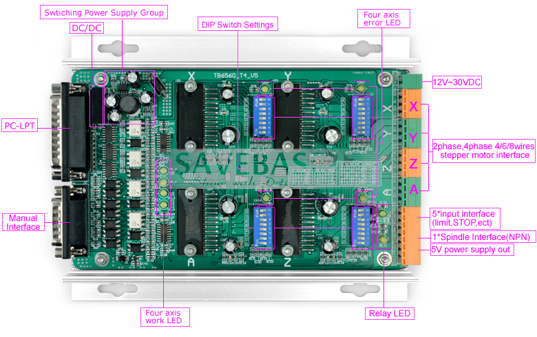
Some wiring and TB6560 Controller Questions
Hey everyone. Just got my SuperPID and am working on wiring it up. I have a TB6560 controller (same as this) and want to get router on/off and PWM speed control through it using Mach3. I’ve been reading through this massive thread and have noted lots of config details. However, I have not found details on how to wire the SuperPID to my TB6560 controller (I’ve seen lots on Gecko units – serve’s me right I guess :-). Anyway, here is what I was thinking:
1) The controller has a 5v output. Just confirming that it is regulated before I use it to power the SuperPID. Question – would it be sufficient to connect the SuperPID 5V GND to the controller GND? I assume that it is also connected to the PC GND through the parallel connection?
2) Wiring Router On/Off and PWM for Mach3. I am using Mach3 and want to control both router on/off and speed using Mach3. (see image below) The TB6560 only lists the following outputs: 1 OUT1 (listed as 1*SpindleInterface NPN) (currently using this to control a relay to switch my DW660 on/off). However, I don’t see any output for PWM. I was wondering if I could solder a connection directly to the parallel port connector (Pin 14 or 17 I believe) and then run it to the SuperPID PWM input? Or alternatively, use the OUT1 as a PWM output and use a switch on the SuperPID to turn the rounter on/off (don’t want this, as I’d rather have Mach controlling this when a job starts/finishes).
3) Also, I have seen various pics of different switches folks have added. I am planning the following: Switch between PWM (Mach3) and the POT. Switch for On/off. Switch for Open loop mode (more of an emergency in case the sensor fails). Any other suggested items to switch (not sure if there are others?)
Thx!
-
02-14-2013, 06:49 PM #2014
Registered
- Join Date
- Oct 2007
- Posts
- 6
 SuperPID to Dewalt DWP611 Setup
Looking for notes/thoughts/ideas on what modifications/steps must be done for connecting up a Dewalt DWP611 to a SuperPID unit. Found lots of information on the Bosch units, but have only found one note on the Dewalt unit.
Specifically wondering about the best ways to sense spindle speed and where people are mounting their sensors to pull the pulses. Also, information on disabling the built-in speed control would be helpful too.
Thanks,
John
-
02-15-2013, 12:48 AM #2015
Gold Member
- Join Date
- Apr 2009
- Posts
- 5516
I go over it in my build thread, in the Project Log section... Originally Posted by jdkerr
-
02-17-2013, 07:41 PM #2016
Registered
- Join Date
- Jun 2012
- Posts
- 0
Could use some help with Mach3 config for PWM
I have an Ebay TB6560 controller. I've got the SuperPID setup and working, but am having trouble getting PWM working from Mach3.
Based on researching a number of posts here, here's my setup:
Motor Outputs Tab: Spindle is set to pin 17 Port 1.
Output Signals Tab: Output 1 Enabled, Port 1, Pin 1.
Spindle Setup Tab:
- Relay control using Output 1 for both directions
- Motor Control: Spindle Motor Output and PWM Control checked
- PWM Base freq: 50, Min PWM 0%.
I can turn the spindle on and off in Mach using the button on the main page. When I run gcode, this feature works fine, but the spindle goes to full speed all the time. I tried entering some direct commands (M3 S5000) to control the speed, but the motor speed stays at full. I ran some gcode that has various speed changes S5000, S10000, S5000 and the motor still goes full blast. It seems that when the router first starts, it is slow, but within a second or two, it quickly goes to full speed.
My controller has Pin 1 dedicated to the output relay, and I confirmed this works. However, it does not have a dedicated output for pin 17, so I soldered a wire directly to the bottom of the parallel port header on the BOB and wired it to the SuperPID PWM pin.
I measured the voltage on pin 17 as ~3.8V (pretty sure it won't change with PWM?). I have a DSO Nano Oscilloscope and here's where I go numb. I got readings, but dont know how to setup the unit to read the pulses to see if they change when I change the speed on Mach3. Any oscilloscope pros able to give me a 101 on this? Else, anyone have any thoughts what I have done wrong?
Thx
-
02-18-2013, 06:31 PM #2017
Member
- Join Date
- May 2010
- Posts
- 102
See my post on this forum link: Build Your Tools ? View topic - Super PID
Within this thread look for my Tue Mar 01, 2011 8:17 pm reply
You will see information that may help you.
Best,airnocker
Everything depends on everything else
-
02-19-2013, 02:06 PM #2018
Registered
- Join Date
- Jun 2012
- Posts
- 0
To help those who may find themselves in a similar situation... I figured out my isssue. (slaps head). Turns out that although I had the SuperPID GND to the controller GND, it was not actually tied to the PC/Parallel port GND) Duh. After some prodding I recalled that the PC side is completely (opto) isolated from the controller. After I tied the GND from the SuperPID to the PC (as well as the power supply), I got a nice clean PWM signal on the DSO. So, I've got Mach now controlling on/off as well as PWM. Let the fun begin... no more melting HDPE at 30K with the DW660. Originally Posted by deejayspinz
-
02-22-2013, 12:54 AM #2019
Registered
- Join Date
- Feb 2010
- Posts
- 52
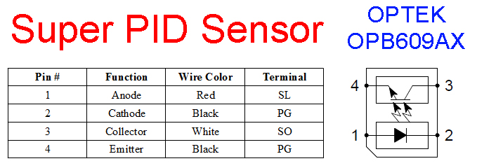
Something took out my sensor. I needed to get up and running today so I bought an Optek OPB609AX and got it going again. Hopefully this info will save someone else a small headache.
-
02-22-2013, 04:24 AM #2020
Registered
- Join Date
- Jun 2012
- Posts
- 817
Thanks for that! I am trying to set up my arduino as a tach (unrelated to cnc) and was wondering what sensor my superpid setup used. Nearly took it apart to find out. Now I don't have to. Originally Posted by ATRepair

 Reply With Quote
Similar Threads
-
Harbor Freight router speed controller fix
By mickelsen in forum CNC Machine Related ElectronicsReplies: 4Last Post: 01-25-2012, 03:46 AM -
Super-PID speed controller installation to Fixed speed Router
By Khalid in forum DIY CNC Router Table MachinesReplies: 14Last Post: 11-13-2010, 11:29 AM -
Super-PID router speed controller
By SuperPID in forum News AnnouncementsReplies: 2Last Post: 10-21-2010, 05:40 PM -
I need a low cost upgrade controller for my CNC Router
By ReefkeeperCNC in forum CNC (Mill / Lathe) Control Software (NC)Replies: 10Last Post: 09-09-2006, 02:01 AM
