


Hi Timnilson.
Is your SuperPID configured to "Knob" mode or "Mach3" mode? If it was ordered for Knob mode it will display a "K" symbol on the display when running, ie; "K-R" on the right hand side of the display. If it was ordered for Mach3 mode it will display "--R".
Can you please check your G540 is wired as per the diagram in the Super-PID instructions, on page 25.
Also please do a simple linearity test if you don't mind;
1. Set everything up in Mach3 as if the router is running, although the router can be unplugged if you like to save on noise and wear.
2. Measure the DC voltage on the G540 pin9 with a multimeter
3. Set mach3 to 5k RPM, then measure the voltage on G540 pin8
4. Set mach3 to 10k RPM, then measure the voltage on G540 pin8
5. Set mach3 to 15k RPM, then measure the voltage on G540 pin8
6. Set mach3 to 20k RPM, then measure the voltage on G540 pin8
(all the voltages are in reference to the SuperPID GND terminal.)
Thanks!
Results 1,981 to 2,000 of 2415
-
12-23-2012, 03:50 AM #1981
 Registered
- Join Date
- Oct 2005
- Posts
- 2392
-
12-23-2012, 04:34 AM #1982
Registered
- Join Date
- Dec 2012
- Posts
- 0
Thanks for taking a look at this with me Roman! Originally Posted by RomanLini

The SuperPID runs in Mach3 mode with "--R" on the SuperPID display while running the router.
1.) With the router running...
2.) The DC voltage on the G540 pin 9 is 5v
3.) Running 5k RPM, the voltage on pin 8 is 0.98v (RPM on DRO is ~5630)
4.) Running 10k RPM, the voltage on pin 8 is 1.74v (RPM on DRO is ~10230)
5.) Running 15k RPM, the voltage on pin 8 is 2.49v (RPM on DRO is ~14900)
6.) Running 20k RPM, the voltage on pin 8 is 2.8v (RPM on DRO is ~17000)
-
12-23-2012, 08:42 AM #1983
Registered
- Join Date
- Jan 2012
- Posts
- 0
Hey guys
I am just about finished installing my Super PID and I was wondering if anyone is running Flashcut software? I'm running a Torchmate machine and they use FC. I need help figuring out how to interface the PID to my control box. I'm pretty sure I have figured out how to get it to turn the PID on and off but I have not figured out how to adjust the rpm from it. If needed I can supply a schematic for the control box and a screen shot of the software. It has an analog output in the menu but I see no way to hook it up. I have tried to contact FC but so far no reply.
Thanks
Kris
-
12-27-2012, 06:22 PM #1984
Registered
- Join Date
- Dec 2010
- Posts
- 64
Blinking R and switching to Pot View
I need help. I am running Super PID rev 2 with EMC2 on my CNC Router with a PC7518 router. I am using only a PWM signal generated by my computer and there is no pot attached.
My Super PID had been running well in all my tests and I ran it for several programs with no issues at all. However, a couple of days ago my router crashed into the workpiece and broke off the bit. After the dust settled, I realized that it was because the router was not running. If it had been, it would have just cut the workpiece normally.
I have done a bunch of testing but I don't know what the results mean. First, when I go into manual mode in EMC2 and turn the router on and off and adjust the speed everything is fine. I can do that all day.
However, if I use the MDI interface and use the M codes or use an actual NC program, to turn the router on and off and adjust the speed, things are hit and miss. When I use M3 to turn it on, sometimes it waits for up to 2 minutes before the spindle turns on. Sometimes, but not very often, it comes on right away. If I include the speed in the same command line such as M3 s5000, I get the same results. After I enter these commands, if I swicth over to manual mode in EMC2, the buttons there show that the command has executed. In other words, after I hit M3, the buttons show spindle on. EMC2 thinks things are good. If I enter M5, those then show spindle off.
What I see on the Super-PID LED confuses me. After I send the M3 command, the "R" on the LED will blink. What does a blinking R mean? Also, I have found that after I stop the spindle with M5, if it never started properly using M3, the LED indicates "pot mode." I do not have a pot on this and I wired it according to the PWM signbal only variatin shown in the Super-PID v2 manual. I do not expect to see pot mode.
So some points of confusion:
-What does the blinking R mean?
-Why does it switch to pot mode when I have no pot and have bypassed that with the jumper as directed?
-Why is the behavior different when I use the manual mode versus program mode or MDI interface? (I had assumed the manual mode just sent an M3 or M5 signal when I hit the buttons.)
I am tired of ruining bits and workpieces. Can anybody help me?
Andy
-
12-30-2012, 12:43 AM #1985
Registered
- Join Date
- Jan 2012
- Posts
- 0
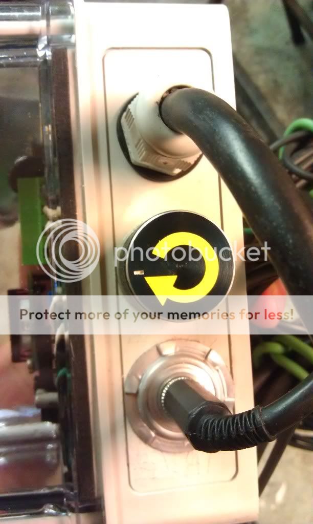
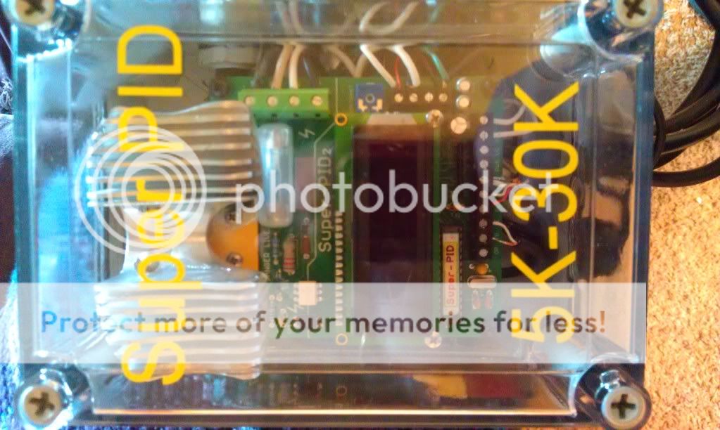
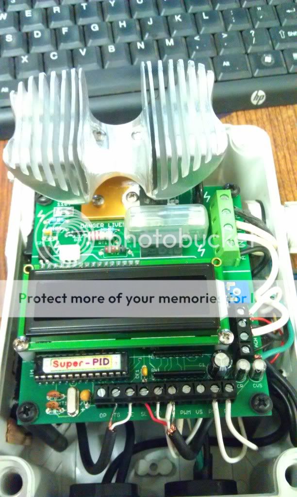
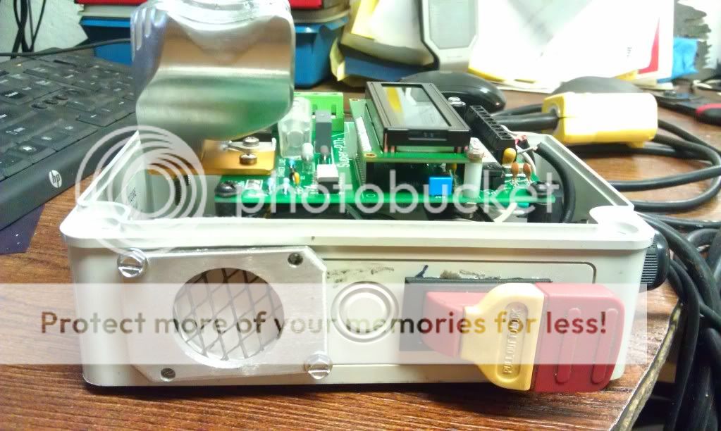
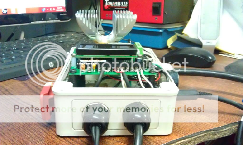
Here are some pics of my setup.


-
12-30-2012, 02:37 AM #1986
Member
- Join Date
- Sep 2011
- Posts
- 1183
Great Pictures nice box I should install mine it has been setting on my work bench for almost a year..

Louhttp://www.cnczone.com/forums/diy-cnc-router-table-machines/140832-cnc-software.html
-
12-30-2012, 06:08 PM #1987
Registered
- Join Date
- Nov 2010
- Posts
- 0
When my budget allows, I will for sure be ordering one of these! Would be very nice to control spindle speed through Mach3. What a great tool!
-
01-01-2013, 07:11 AM #1988
Registered
- Join Date
- Oct 2005
- Posts
- 2392
Hi Andy, sorry to hear you are having some problems there. Originally Posted by ameinert
I think the blinking "R" is a good indicator something is wrong, and fault finding should start there. When the SuperPID RUN terminal is high at 5v, the router will be stopped and the "R" is not displayed. When the RUN terminal is activated with a low signal (0v) the router will start to run and the "R" is displayed.
The only thing that will make the "R" display blink on and off is if the signal going to the SuperPID RUN terminal is bad, like a loose connection, or getting a lot of noise on that wire, or if the signal itself is switching on and off very fast. The SuperPID has software debouncing on that terminal so for it to blink on and off there is something very wrong with the signal that is going in to the RUN terminal.
I'm not sure which way you have wired the speed control interface, if you can say whether you wired from the parallel port or breakout board that info will help. Also if you used a page from the SuperPID datasheet as a wiring guide please say which page.
From your symptoms I think somehow you have a very bad connection, or mis-wired the pulsing PWM signal from Mach3 to the SuperPID RUN terminal.
To Stalthshooter- Hi, and thanks for all the great photos! That heatsink is amazing, I have never seen that style before. It's probably much bigger than is needed but that never hurts in an electronics device, the cooler the better is a general rule.
(edit) Whoops! Forgot to wish all you guys a great holiday season and a Happy New Year!
-
01-01-2013, 10:20 PM #1989
Registered
- Join Date
- Nov 2010
- Posts
- 520
Mains switch
So I am putting together my enclosure and was thinking about a switch to control the main power supply (120v AC) to the SPID. Basically to shut it down at the end of the day.
TIA.
Rick
-
01-01-2013, 11:44 PM #1990
Community Moderator
- Join Date
- Dec 2003
- Posts
- 24223
IMO, the power source for equipment fed from a common enclosure and central supply is the preferred method.
This allows a single disconnect and the source of power to all of the machine, also is easier to implement a single E-stop source for power rather than feeding separate parts of the machine off of different outlets.
This is the way it is implemented in commercially supplied equipment.
Al.CNC, Mechatronics Integration and Custom Machine Design
“Logic will get you from A to B. Imagination will take you everywhere.”
Albert E.
-
01-02-2013, 06:42 AM #1991
Registered
- Join Date
- Jan 2012
- Posts
- 0
Thanks RomanLini
The heat sink is out of an old computer . It was way too big to fit where I needed it. I took the band saw and sander to it and custom fit it LOL. I'm in the midst of deciding weather to keep my flashcut system of change to a mach3 system. The Flashcut seems to be nice stuff but it has a lot of things lacking that I would really like and it will cost more to upgrade them than it will to just start over.
-
01-05-2013, 01:15 AM #1992
Registered
- Join Date
- Dec 2010
- Posts
- 64
Thanks for the reply, RomanLini. Originally Posted by RomanLini
What you said seems reasonable except that there was obviously a software component to the effect. The confounding part of the problem is that the behavior was different depending on how I sent the "On" signal from the Linuxcnc software. So it seems like that signal out gets to the Super-PID fine when I sent it one way, but not consistently when I do it another way. To me, that means there's a difference in the signal that is being sent and not just my crummy wiring job. (My wiring job may be crummy. I am new to this.)
Ultimately, someone on the Linuxcnc forum suggested I turn on a status screen. Doing so showed me that when Linuxcnc sends the spindle on signal from the manual mode, it sends speed value of 1 (as in 1 RPM). I was always sending 5000 or 12000 or something like that. So, I went back and tried to always turn it on first using S=1 and it works. The router goes to its minimum 5000 RPM speed. Once the router gets turning I can set speed to whatever I want and everything is normal. I am just editing my templates to include a "M3 S1" line at the beginning and for now I include a "G4 P5" dwell command so that the machine waits 5 seconds before it moves. The cnc software then sets the speed to the right value in the next line anyway.
So I have resolution but it is still kind of odd how it works.
I am really happy with the Super-PID. It really enhances the machine I spent so much time designing and building.
Andy
BTW - I am using the PWM signal variation that is shown on page 23 of the v2 manual.
-
01-09-2013, 07:31 PM #1993
Registered
- Join Date
- Dec 2010
- Posts
- 0
back from vacation
decided to do some work on my bbox
I have mounted the SuperPID in a plastic enclosure
it's only temporary as it needs to be bigger
but at least it keeps mains voltages away from tools and fingers
I have set it up to be controlled from my controller box
- 5 volts for the electronics
- 12 volts for the fan
- run signal
- PWM speed signal
wired it all up, but being careful I decided to connect the 5 volts first
I figured 5 volts wouldn't hurt the fan if I wired it wrong
but 12 volts might be bad for the electronics
I was right
managed to connect the 5 volt wire to the 12 volt supply
SuperPID was very bright!
noticed that something was wrong - hot electrons have a distinctive smell
so powered everything down very quickly
sadly not quickly enough to stop the magic smoke from escaping fom something
when I powered the SuperPid up with 5 volts
a) the display was fragmented
b) only one side of the display was working
I did try the technician's magic words, but to no avail
luckily I have some identical displays, so more in hope than certainty I replaced the display
it works
full display capability restored
re-connected sensor and pot - they're still working too - phew!
the run signal from the gcode interpreter is also functioning correctly as well
electronics now back in the box
yet to try the mains side, thought a brief period of thought before venturing out again
supper calling
brb
-
01-09-2013, 08:24 PM #1994
Registered
- Join Date
- Dec 2010
- Posts
- 0
hmm
update
tried a small gcode program
M3 start motor (pot for speed)
G1 move a bit
M5 stop motor
good news is M3 does start the motor
SuperPid says
- "looking for mains"
- 50 Hz found (UK so that's correct)
- Starting motor
motor winds up, then SuperPID says
- "motor start failed"
then turns off the power
I've tried rotating the spindle by hand, SuperPID reports high and low as expected
wah :drowning:
anyone got any ideas?
-
01-09-2013, 08:59 PM #1995
Community Moderator
- Join Date
- Dec 2003
- Posts
- 24223
Sounds like the sensor may not be reading??
You must be picking up the input power with the M3?
I still think the most practical (and safest) is the way I set it up with contactor on the power output from sPID to motor, and an auxilliary contact for the start/enable, instead of picking up the input power every time, and having to go through a start up procedure.
This also allows a safe way of tool change.
Al.CNC, Mechatronics Integration and Custom Machine Design
“Logic will get you from A to B. Imagination will take you everywhere.”
Albert E.
-
01-09-2013, 09:04 PM #1996
Registered
- Join Date
- Dec 2010
- Posts
- 0
Al Originally Posted by Al_The_Man
I thought sensor too, but turning the spindle by hand the sensor shows highs and lows just like it used to do
fair point about the contactor on the output power
M3 is simply commanding the SuperPID run input
I tried setting that by hand (with a wire)
it worked ok when I first got the SuperPID
it now does the same as M3 - motor starts but SuperPid doesn't think the motor is running
odd that the sensor is ok at low speeds, but not at high speed?
-
01-09-2013, 09:17 PM #1997
Community Moderator
- Join Date
- Dec 2003
- Posts
- 24223
Incidentally, it looks like a typo in the V1 SuperPID manual for the RUN-OFF command, between pages 6 & 7, they declare the opposite, at least that is the way I read it??
V2 looks OK.
Al.CNC, Mechatronics Integration and Custom Machine Design
“Logic will get you from A to B. Imagination will take you everywhere.”
Albert E.
-
01-09-2013, 09:20 PM #1998
Registered
- Join Date
- Dec 2010
- Posts
- 0
I have a V2 Originally Posted by Al_The_Man
manual says
connect RUN to Ground to start,
disconnect to stop
seems to work that way
motor does start, but I have to admit it sounds like sensor not working at high speed
-
01-09-2013, 10:40 PM #1999
Registered
- Join Date
- Dec 2010
- Posts
- 0
curioser and curioser
tried two more tests
1st test
comand RUN and just see what happens
motor starts to turn
gets faster and faster (way beyond 5k set on pot)
PID say - start failed, power off
as motor slow sensor reading appears
so PID start up again
GOTO step 1
rinse
repeat
maybe sensor just doesn't work at high speeds
2nd test
RTFM
noticed Open Circuit mode
let's give that a try
motor speed responds nicely to pot position
so all is not completely lost
just need to figure out why the sensor doesn't work at high speed
haven't changed anything
well almost nothing
sensor now comes into the PID enclosure via a 5 pin socket
might try removing that from the equation tomorrow
-
01-12-2013, 03:07 PM #2000
Registered
- Join Date
- Mar 2007
- Posts
- 28
Just curious, how much spread are you getting between your "high" and "low" from the sensor when you turn the spindle by hand? If the difference isn't far enough apart then it could cause the problem you describe. also what material are you using for the white, black on your spindle? I tried the "white out" that I read about but discovered that it didn't stay on my spindle very well, it fragged apart in short order, so I used some sign painters paint that I had, and also colored the balance of the spindle black with a permanent marker because i was getting reflections from the bare metal. And finally adjusting the sensor to get it close enough is crucial, my readings now run form nearly zero to nearly full bars and I have been running it for about a year now with no problems at all. Hope that helps

 Reply With Quote
Similar Threads
-
Harbor Freight router speed controller fix
By mickelsen in forum CNC Machine Related ElectronicsReplies: 4Last Post: 01-25-2012, 03:46 AM -
Super-PID speed controller installation to Fixed speed Router
By Khalid in forum DIY CNC Router Table MachinesReplies: 14Last Post: 11-13-2010, 11:29 AM -
Super-PID router speed controller
By SuperPID in forum News AnnouncementsReplies: 2Last Post: 10-21-2010, 05:40 PM -
I need a low cost upgrade controller for my CNC Router
By ReefkeeperCNC in forum CNC (Mill / Lathe) Control Software (NC)Replies: 10Last Post: 09-09-2006, 02:01 AM
