


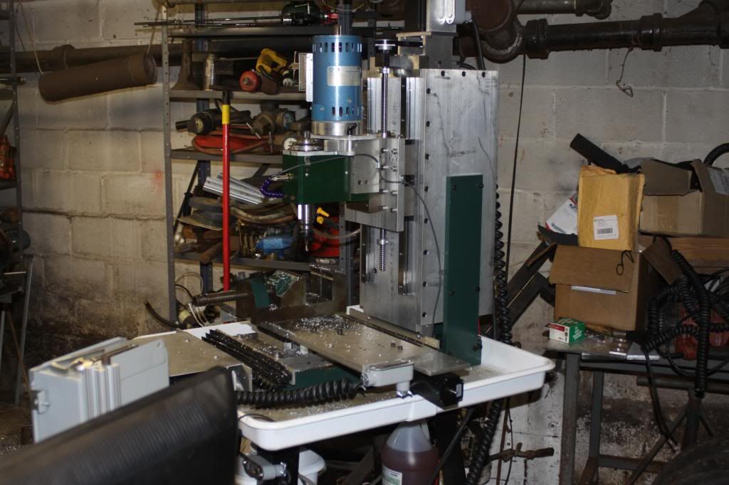
This morning I changed out the test setup for a plate and section of bar that is actually bolted to the slide table instead of c-clamped to the plate. The problem must have been flex in the c-clamps because now I am measuring a deflection of less than 0.00025" with 15.24 pounds of force applied at 10 inches from the centerline of the slide. This translates into a stiffness of 60,000 pounds/inch which is well within the range for acceptable milling of aluminum. If all three axis had worst case 0.00025" deflection at 10 inches from the slide then the stiffness would still be in the 20,000 pounds/inch range (not sure exactly how they might add up but seems a reasonable guess). This is still acceptable for aluminum, especially with a small high speed cutter as the tables can move at many hundreds of inches per minute.
So having determined that the slides are decent for the amount of work (read zero) involved in setting up motors, ballscrews, linear ways and limit switches, I think the plan of attack is to come up with a configuration that gives the most rigidity for the largest travel in all three axis while keeping the overall weight down. I still think the classic c-frame xyz mill is probably the way to go. I am looking around at the few build threads that used linear bearings in a c-frame construction and note that they usually made a box or at least u shaped structure for the column. I have a big plate (36" x 24") of 6061 T651 1" thick aluminum that I would like to use for the base and column. I wouldn't have a problem with filling the column with epoxy granite if vibration dampening was still needed.
I am going to modify my drawing to extend the column higher to encompass 10 of the mounting bolts on the linear slide back, and instead of the forward triangle gussets, I am going to use 1 inch thick side plates to form a U-channel column supported all the way up. It is either this method or try a weldment of thick walled rectangular steel tube, but talk about heavy!
Results 1 to 16 of 16
Hybrid View
-
08-08-2013, 03:52 PM #1
 Gold Member
- Join Date
- Dec 2005
- Posts
- 484
-
08-08-2013, 08:41 PM #2
Gold Member
- Join Date
- Dec 2005
- Posts
- 484
Taking some advice from you guys I reconfigured the drawing to have X and Y use the 500mm travel linear modules and Z use the 300mm travel module. This did have the advantage of making the Z axis seem more reasonable in height relative to the machine. I also moved the Z axis and column support up and over the Y slide such that there is 2 inches of clearance between the top of the tooling plate where the work would fasten and the bottom of the Z axis linear module. This gains you about 90mm in Y travel for relatively thin items like panels...things that tend to use up Y axis travel. Obviously the 2" wouldn't be good for a vice, but if you are using a vice, then you probably are not needing more than 6 or 8 inches in Y travel on that part. This seems like an excellent compromise between getting the most Y and maintaining high rigidity and a traditional xyz mill configuration.
As drawn, the (fake, representative) spindle center has 13.5 inches of clearance to the column the z axis is mounted and sticks out 10 inches from the z axis slide. I used this distance and number because those were deflection test results and give me a good idea of what a reasonable spindle distance might look like for machining aluminum. For an even stiffer configuration, perhaps removing a spacer block or something to reduce the distance to the z-axis while cutting those harder materials.
The rear columns are 1 inch plate...I plan to use 6061 T651 because I have a 2 foot by 3 foot piece. I do not know how I will tap the end holes in the blue part to enable it to be bolted to the baseplate. Even my Shizuoka doesn't have that type of boring capacity...hand drill? This is the case where I could use a knee mill with 40 inches of Z...
You can see in the last pic with the Z up at it's highest point and the X and Y moved back from Z that the Y travel of 20 inches is now not really useable. I can probably capture a good 14 to 16 inches of it with a reasonable spindle length but getting all 20 inches would require quite the long spindle spacer block. Perhaps I can one day trade a 500mm slide for a 400mm slide...but mine are unused new in the box so very attractive to use.
This feels very easy to build and doable...except for the blue column supports and their tapped holes on the bottom.
The mill would have rapids of over 1000IPM, resolution of 1.25um, precision NSK ground ballscrews, NSK rails and carriages, 300 watt brushless servos.
I have about $500 total in the slides...they were quite the steal which is why I bought so many. At some point I will have to sell the rest...or maybe build a 2nd machine and sell it...
-
08-09-2013, 01:59 AM #3
Gold Member
- Join Date
- Dec 2005
- Posts
- 484
Ok, a little more thought and refinement.
I decided to narrow the bottom baseplate such that the z axis column supports (shown in blue) would attach from the sides at all points. This eliminates the need to drill and tap a hole in the end of a > 20 inch length part. This does mean the baseplate needs tapped holes in it's sides, but being only 8 inches wide, this is easily doable on the Shizuoka (has a 20 inch Z travel).
I have also added a cutout in the column support where the adept servo motor power and encoder/limitswitch cables exit the module. It is a small cutout but I didn't want to remove too much material from such an important structural component. Should be able to painfully screw and unscrew the connectors, perhaps with help of soft pliers. All of the other axis modules have the end with the cables in the clear.
On the z axis column supports, I added a short rear plate near the bottom and two gussets? in between sets of bolts that attach the z axis linear module to the column. This should give some stiffening without blocking access to the module mounting screws. I know someone is going to say fill the z axis with epoxy granite, but the difficulty here would be all of the (12 of them) bolts that attach the z axis module to the plate. You would have to create 12 deep channels that the epoxy poured around so you could remove the module for any repairs. Nothing prevents going to this effort at some time in the future if I find that all of the 1 inch thick plates and gussets still don't provide stiffness and dampening of vibrations.
I may attach some feet to the base as it will be bolted to a worktable. I should remember to drill/tap some holes for those.
See any potential gotchas so far? It looks like it is becoming fairly beefy while still maintaining a compact size but I am open to suggestions. I really want to keep the classic C-frame milling machine look and travels though.
-
08-09-2013, 03:00 PM #4
Gold Member
- Join Date
- Dec 2005
- Posts
- 484
One more change.
I calculated the 2 foot by 3 foot by 1 inch thick plate of 6061 T651 would not be enough for all of the parts so I will be ordering some Alimex cast and ground aluminum plate from Midwest Steel. It sounds similar to Mic6 and I have read a few threads about people who have used it. I will use it for the baseplate and the green color plate in the column where the z-axis bolts. The blue column uprights will fit into the 6061 T651 plate I already have, as will the webbing.
Because I have to order aluminum anyway, I decided to increase the baseplate thickness to 1.5 inches and machine a pocket for the blue color Z axis supports. They will still bolt into the sides of the baseplate but now will have a machined surface on the side and bottom for easier alignment. This also provides a place to put a shim if needed to get the z-axis column and baseplate a perfect right angle. The increase to 1.5 inches on thickness can't hurt rigidity of the whole mill either.
-
12-07-2013, 09:13 PM #5
Registered
- Join Date
- Jun 2008
- Posts
- 467
KTP,
Have you made any progress on this project?
JoeyBA doughnut a day keeps the doctor away.
-
12-07-2013, 10:57 PM #6
Registered
- Join Date
- Apr 2013
- Posts
- 97
I don't know about the strength of your linear slides. He is a picture of the one I built with standard aluminum plate. And a cast-iron right angle plate. Plus steel flat stock check out my posts for the build here is a picture. The week point of mine was I got used linear rails and bearings from eBay for the X and Y they are not preloaded and have a little bit of play. But if I invest some new bearing blocks should be very good

 Reply With Quote
Similar Threads
-
All Parts "Off-the-Shelf"
By Plan_B in forum CNC Wood Router Project LogReplies: 15Last Post: 07-16-2011, 02:20 AM -
Mini Mech Mate - off the shelf parts
By nguyenst in forum CNC Wood Router Project LogReplies: 50Last Post: 03-16-2010, 07:52 PM -
proseries bedmill
By sindychen in forum News AnnouncementsReplies: 4Last Post: 12-21-2009, 02:42 AM -
Simple Printing on Vinyl with basic inkjet printer
By FrmDstryr in forum Printing, Scanners, Vinyl cutting and PlottersReplies: 9Last Post: 10-23-2008, 03:15 AM -
Assemble linear-actuator using off-the-shelf parts for < $600?
By offtherack in forum Linear and Rotary MotionReplies: 3Last Post: 04-22-2008, 08:42 AM
