


The Beams should machine where needed very well alsoOriginally Posted by jono5axe
 Thanks, it is good when there is finally something to see for the work.
At that stage now, will make some decisions this week.
Yes, it worked out pretty much as planned.
- the cross section of the steel RHS is now stabilised.
- the internal components are all fixed in place by the epoxy mix.
- vibration dampening seems very effective from what I can determine at this stage. If I knock the beams with a wooden mallet it makes a very muted dull thud, whereas if I knock an unfilled large RHS section with the mallet it rings like a church bell in an echo chamber.
But, something to consider, the epoxy concrete part of it was quite a lot of work and time consuming (but I suppose everything has been quite a lot of work, everything has more detail that consumes more time than I had planned).
Mix used was:
- aggregate = 1/3:1/3:1/3 of sand, 7mm & 13mm (by volume)
- plus resin at 8% of aggregate by weight.
Each main beam has approx 300kg of epoxy concrete in it. Hopefully we will see some benefit from it when trying to cut good surface finishes on 3D shapes in duratec'ed and/or aluminium patterns.
Results 41 to 60 of 87
-
04-29-2018, 06:10 AM #41
 Member
- Join Date
- Jan 2005
- Posts
- 15362
Re: Large Format 5-Axis Gantry Router
The Beams should machine where needed very well also Originally Posted by jono5axe
Mactec54
-
05-01-2018, 10:54 PM #42
Registered
- Join Date
- Jun 2014
- Posts
- 0
Re: Large Format 5-Axis Gantry Router
Just keeps getting better Jono! This is going to be a monster! Really looking forward to it cutting some material!
-
07-31-2018, 09:15 AM #43
Registered
- Join Date
- Oct 2016
- Posts
- 65
Re: Large Format 5-Axis Gantry Router
Re-reading some earlier threads on composites stuff and thought to post these pics of what a temporary oven/hotbox looks like.
Inner skin of foil faced foam, outer of clear plastic, on a timber frame. Thermocouples on the part inside the hotbox. 60 degree Celsius post cure. Fan heaters.
5.5 meter hotbox, was used our router gantry beam.
Jonathon Clarke
www.solpont.com
-
01-24-2019, 06:31 AM #44
Registered
- Join Date
- Oct 2016
- Posts
- 65
Re: Large Format 5-Axis Gantry Router
Back to work on this now. Did not progress on it for the last six months, but will hopefully be posting some regular progress from now on!!! The clock is ticking.
Just finished bolting up the removable front cross-beam. I can drive the 2.5T Forklift (container mast) under the cross-beam, but it can be removed if necessary for loading really big jobs (!?!?)
Please excuse the messy workshop...
Jonathon Clarke
www.solpont.com
-
02-06-2019, 10:24 PM #45
Registered
- Join Date
- Aug 2014
- Posts
- 232
Re: Large Format 5-Axis Gantry Router
Excellent thread, I'm enjoying it.
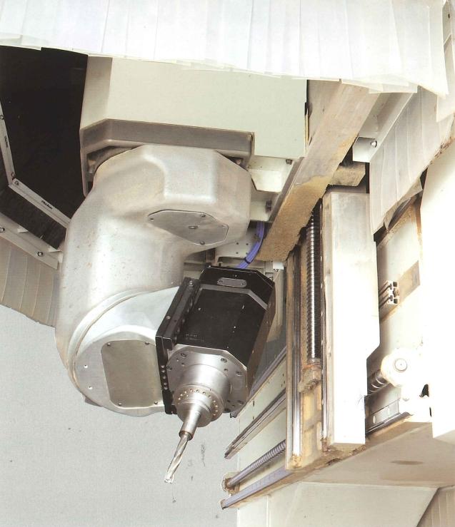
Have you considered a nutating head ? I have one on a 5 axis Morbidelli ( also HSK63F ), it's rigid and compact.
-
02-07-2019, 10:26 AM #46
Registered
- Join Date
- Oct 2016
- Posts
- 65
Re: Large Format 5-Axis Gantry Router
Hi there. Is that an available package? If so, where from? What is that spindle? What is the Z travel on that machine? I had only seen flat panel Morbidelli machines, but that is obviously something different than a flat panel router.
Yes, I did consider that head format, pros & cons etc. I think recall that the main advantage (45 degrees) was being able to get in a bit tighter on the workpeice in some situations, which increases the machining envelope of a given machine (?). As I am not experienced at motion control I decided to go with (what seemed to me) the simpler 90 degree setup. It also seemed that there was more information out there for me to use if I run into setup/software/programing problems. I will make up some sort of IP67 bracket arm, maybe from composites, or just aluminium profiles. The 90 degree setup is also quite straight forward to locate the servos in the assembly using belt drives onto the harmonic drives.
But please let me know if there is some major advantage with the 45 degree setup. As I say, I had to make a decision from a fairly uninformed start point, so I did a bit of research and came to a (moderately) informed decision.....
I have the spindle, harmonic drives & servos already, based on a 90 degree setup. They were sized on calculation, starting with the torque I wanted in the harmonic drives (torque on the tool tip) and then comparing/checking what the big name machine suppliers use. I think I based my calcs on each axis being able to get through (rapid) 360 degrees in 1.0 second. A lot of the machines that I have seen cutting in simultaneous 5 axis mode seemed to be limited by slow A & C axis movement, and I wanted better than that. But it will only be proved in the pudding, of course.Jonathon Clarke
www.solpont.com
-
02-07-2019, 08:06 PM #47
Registered
- Join Date
- Aug 2014
- Posts
- 232
Re: Large Format 5-Axis Gantry Router
The machine is an Author X5, mine is about 15 years old but still going well. They call the spindle Prisma, it's 11kw / 15hp, 18000rpm. X axis 3200mm, Y 1300 ish, I can fit 250mm between the guards and pods / rails, but larger work is possible if you get creative with workholding.
The nutating head does allow a good work envelope and is very rigid. The spindle axis is very close to the outside diameter of the spindle, so it's possible to get the tool close to the pods / rails. I machine aluminium and Delrin on it regularly, the finish is almost as good as on the VMC.
-
02-08-2019, 01:22 AM #48
Registered
- Join Date
- Oct 2016
- Posts
- 65
Re: Large Format 5-Axis Gantry Router
Hi Zorbit. What CAM do you use for simultaneous 5-axis machining?
Jonathon Clarke
www.solpont.com
-
02-08-2019, 09:46 AM #49
Registered
- Join Date
- Aug 2014
- Posts
- 232
Re: Large Format 5-Axis Gantry Router
Hypermill 2018. Expensive, but good. A few years ago I considered building a machine similar to yours, to make moulds for small yachts, and at the time Delcam looked like the best bet.
-
03-14-2019, 09:33 PM #50
Registered
- Join Date
- Oct 2016
- Posts
- 65
Re: Large Format 5-Axis Gantry Router
I think that I can officially declare that self leveling epoxy sucks.
Maybe for small areas it is ok, but for longer beds it is just not possible to get it to flow out flat enough. Even when being very exact with putting the right amount in specific zones to ensure that the required flow is minimal and just local leveling is sought, I am still getting poor results. If I am not careful I can get high/low spots of +/-1.0 mm or more (which is I presume the form of a frozen flow wave) but even a good pour is high/low of +/- 0.1 mm or more over 300mm spans. Epoxy is a special low viscosity resin and gel time is two hours so that is all fine. Lots of hand work required (precision hand sanding, staight edge, precision level checking) to get it in any kind of shape. Across the bed is OK (level and flat) but longitudinally is rubbish.
[Note: I am putting a gauged plate on top of the epoxy when flat. This plate follows the faults in the epoxy to a degree, for example +/- 0.05mm over 300mm]
Question:
Regarding flatness of beds for linear rail mounting (medium precision/preload) can anyone please tell me tolerances for flatness. Generally the linear rail manuals do not state tolerances on the bed flatness requirements, just stating "flat and straight mounting surfaces". I have found various info that would suggest max allowable values of 0.02mm out of flat over 500mm (for medium precision/preload rails up to 45mm) but this maybe seems a bit extreme to my thinking. Please if anyone has any knowledge here I would be grateful to hear it.
At the moment it looks like I have a lot of hand scraping ahead of me.Jonathon Clarke
www.solpont.com
-
03-14-2019, 09:37 PM #51
Member
- Join Date
- Apr 2004
- Posts
- 5752
Re: Large Format 5-Axis Gantry Router
It sounds like your epoxy was too viscous. I'd suggest scraping it off and trying again; this time thin it with some acetone until it levels out immediately.
-
03-15-2019, 03:18 AM #52
Registered
- Join Date
- Oct 2016
- Posts
- 65
Re: Large Format 5-Axis Gantry Router
What flatness values are you measuring with that method awerby?
Jonathon Clarke
www.solpont.com
-
03-15-2019, 07:25 AM #53
Member
- Join Date
- Apr 2016
- Posts
- 841
Re: Large Format 5-Axis Gantry Router
Heating both parts of the epoxy to about 115 degrees F, and then combining them, will reduce viscosity. On the downside, it will cause the mixture to set up faster.
The preferred method, according to the folks at West Systems, is to heat the substrate and then add the epoxy at room temperature. The warmed metal will reduce the epoxy's viscosity and help it flow out. One problem, though. Your machine is a huge beast that probably needs several people to mix and pour at about the same time. It might be worth talking to the folks at West Systems for suggestions. Their international phone number is 1-989-684-7286. They are open 9:00 am to 5:00 pm US Eastern time. I believe that translates to 2:00 am to 10:00 am NZDT a day later.
-
03-15-2019, 11:43 AM #54
 Member
- Join Date
- Jul 2018
- Posts
- 6501
Re: Large Format 5-Axis Gantry Router
Hello Jono - sandwich structures are only stiffer in the thru thickness direction. Their global stiffness is actually less then if you only had the fibres on the outside. Sandwiches are great for boats that have to keep water (thru thickness pressure) out but not good for things like beams such as you are making. The only reason to make a sandwich in that case is to control local buckling. But your structure will not buckle in this application. There is also a comment to add acetone to make the epoxy thinner do not do this! The acetone is non functional and takes up volume within the epoxy. It then desorbs out of the epoxy over time and the epoxy shrinks. So your surface will change!! cheers Peter s
-
03-15-2019, 12:07 PM #55
Registered
- Join Date
- Aug 2014
- Posts
- 232
Re: Large Format 5-Axis Gantry Router
Acetone can also inhibit the cure - so it remains permanently weak. I tried it some years ago to see if I could achieve very deep penetration into wood.
-
03-16-2019, 04:02 AM #56
Registered
- Join Date
- Oct 2016
- Posts
- 65
Re: Large Format 5-Axis Gantry Router
Thanks for the comments Peter. I understand what you are saying, but i can say that: Originally Posted by peteeng
1) Most fibre is in fact on the outside.
2) the method of constructing a large beam without a mold utilises the core to support for the fibre/laminate during construction.
3) The skins need stiffness themselves, in order to mount precision equipment (linear bearings, gear racks).
4) The critical consideration for the gantry beam is deflection in torsion (rather than bending) and I consider that my nice stiff sandwich rectangular-hollow-section is going to have less deflection than a floppy thin skin rectangular-hollow-section in torsion (bigger moment of gyration?). [circular section would be more pure solution, but not ideal for mounting rails on.]
5) I wanted thickness/stiffness/substance to counteract resonance. Thin skin would be like a drum.
6) I like my sandwich.
Ps Acetone added to epoxy >> degraded cure and degraded mechanical properties of cured resin, and porosity.Jonathon Clarke
www.solpont.com
-
03-16-2019, 11:26 AM #57
Registered
- Join Date
- Mar 2009
- Posts
- 39
Re: Large Format 5-Axis Gantry Router
Hallo jono
Very interesting and ambitious project here.The scale is impressive.
On epoxy leveling ukcnc seems to be the forum where epoxy leveling is the go to method.Those builds go into considerable detail.
If I recall accurately this build has some good detail as a starting point.
BUILD LOG: A sufficiently strong machine
I wish you good problem solving on this project.
Robert.
-
03-16-2019, 11:32 AM #58
Registered
- Join Date
- Jan 2008
- Posts
- 1543
Re: Large Format 5-Axis Gantry Router
How thick is your epoxy pour?
I found I needed quite a thick layer. A good 5mm. I remember reading a recommendation for 1/4" (6.35mm) thick layer - can't find the source however.
There is a fair bit of surface tension.
Sent from my SM-G970F using Tapatalk7xCNC.com - CNC info for the minilathe (7x10, 7x12, 7x14, 7x16)
-
03-16-2019, 11:36 AM #59
Registered
- Join Date
- Jan 2008
- Posts
- 1543
Re: Large Format 5-Axis Gantry Router
The linear rail spec sheets will have specifications for all the allowable tolerances.
What matters is that the two rails are equal. That is why spec sheets don't concentrate on flatness - they talk about parallelism and height tolerance.
Sent from my SM-G970F using Tapatalk7xCNC.com - CNC info for the minilathe (7x10, 7x12, 7x14, 7x16)
-
03-16-2019, 11:51 AM #60
Member
- Join Date
- Jul 2018
- Posts
- 6501
Re: Large Format 5-Axis Gantry Router
Hi Jono - I suggest you do a torsion proof test and measure its torsional deflection. I doubt if the bending stiffness will be the weak link as you say. Then back calculate the bulk shear modulus for the beam and see how you do compared to other structures eg riveted aluminium or steel (like aircraft construction) You'll only have one good opportunity to do this before you build it into the machine then you will know if you have made a good structure. The structure you describe has a small shear modulus and being square is not geometrical ideal. Then you'll have good info for when you build your next machine. I've been involved with composite structures for about 30 years and understand why you would build this way. Composite are great but they need to be executed correctly to get high mechanical properties. These days it's quite easy to get aerospace grade laminates in your garage using infusion methods.
The discussion about mass as a damper is an interesting one. Adding mass is the easiest method to damp a structure, its harder to excite a heavy thing then a light thing. But if you want it to move fast this is a poor method as then you need more power to accelerate it. You won;t get a job in an F1 team or a Boeing design team if you say "let's add some mass here" So using the add mass approach we would make suspension elements on cars heavier or at least make the car heavier which is what the old american cars did. But if you want a performance structure then you have to lightweight the hell out of it and solve the resonance problem (if there is one) another way. There are many ways to dampen a thin structure, from adding creases, to adding soft stuff to it, to adding tuned dampers, to active dampers etc etc. If you want to up the game you have to up the technology. Cheers Peter S

 Reply With Quote
Similar Threads
-
Best DIY kit to convert for Large Format Foam 3D? How to ad 4th axis? 8k-10k?
By untametycoon in forum DIY CNC Router Table MachinesReplies: 5Last Post: 05-24-2015, 06:12 PM -
Advice and help needed for large format mill with gantry
By cnccnc222 in forum Uncategorised MetalWorking MachinesReplies: 88Last Post: 03-07-2014, 06:44 PM -
Denford Large Format Router with ATC
By Kitsamus in forum News AnnouncementsReplies: 0Last Post: 04-13-2011, 02:18 PM -
Heavy large scale gantry mill/router/3d carving 5 axis build
By Tristar500 in forum DIY CNC Router Table MachinesReplies: 20Last Post: 03-18-2010, 12:07 PM -
Higher End Large Format Router Mill Project
By jsage in forum Open Source CNC Machine DesignsReplies: 56Last Post: 02-24-2007, 04:58 PM
