


There are hundreds of Avid / CNCRP machines running and making things everyday that are set up that just way.Originally Posted by nlancaster

Results 41 to 60 of 99
-
08-09-2019, 02:11 AM #41
 Member
- Join Date
- Sep 2005
- Posts
- 1740
Re: CRP4896 Standard to Linear Rail Conversion
Retired Master Electrician, HVAC/R Commercial. FLA Saturn 2 4x4 CNC Router Mach4 Kimber 1911 45ACP
-
08-09-2019, 03:24 AM #42
Member
- Join Date
- Feb 2005
- Posts
- 829
Re: CRP4896 Standard to Linear Rail Conversion
exactly!
-
08-09-2019, 04:39 AM #43
Member
- Join Date
- Apr 2016
- Posts
- 841
Re: CRP4896 Standard to Linear Rail Conversion
Originally Posted by nlancaster
Your being satisfied with the methodology your using is what counts. You are the one who will be using your machine. I'm just an old guy who's probably too much of a perfectionist, and who suffers when I fail to attain what I'm going for. For folk like me, perfectionism is both a blessing (when things go right) and a curse (when things go wrong).
Originally Posted by wmgeorge
Maybe thousands sold by now in total, but who's counting?
I agree with your assessment. I suspect the vast majority of owners bought their machines to cut wood (they are routers, after all). For many, getting to within 1/32" is acceptable in woodworking and even a machine put together so-so, will probably achieve a 1/32". For signs, plaques and other parts that don't have to fit together, most probably wouldn't notice the effects of less-than-perfect machine assembly or an even greater than 1/32" tolerance. Get into cutting dovetails and inlays, or large fit-together parts like large cabinets, the more precision the better IMO. It all depends upon what folks want their machine to do and what they they find acceptable. To each his own.
Gary
-
08-09-2019, 07:03 AM #44
Member
- Join Date
- Feb 2005
- Posts
- 829
Re: CRP4896 Standard to Linear Rail Conversion
We have built boats with my existing machine.

-
08-09-2019, 09:29 AM #45
Member
- Join Date
- Apr 2016
- Posts
- 841
Re: CRP4896 Standard to Linear Rail Conversion
Very cool. What kind of boats? Where did you get your lofting plans? I want to make half hull models of some classic sailboats, e.g., Bluenose schooner. On the CNC, of course. I've looked around some for plans, but I haven't had much luck finding them. I've been playing with CAD and think I may be able to transfer lofting to the computer without cost prohibitive specialized marine architect software. Originally Posted by nlancaster
I'm sailboat guy. Back in my younger days, I sometimes crewed on larger racing boats. Mostly filling in when a regular crew member couldn't make it to a race. What a hoot!
Gary
-
08-09-2019, 06:34 PM #46
Member
- Join Date
- Feb 2005
- Posts
- 829
Re: CRP4896 Standard to Linear Rail Conversion
My dad has built 2 canoes, 2 rowboats, a paddleboard, and currently a power boat, with parts from the cnc router.
He is also in the process of building a 34ft live aboard sail boat.
The plans all came from my dad, designed in solidworks.
-
08-09-2019, 08:18 PM #47
Community Moderator
- Join Date
- Mar 2003
- Posts
- 35538
Re: CRP4896 Standard to Linear Rail Conversion
He must have a lot of free time...
Gerry
UCCNC 2017 Screenset
http://www.thecncwoodworker.com/2017.html
Mach3 2010 Screenset
http://www.thecncwoodworker.com/2010.html
JointCAM - CNC Dovetails & Box Joints
http://www.g-forcecnc.com/jointcam.html
(Note: The opinions expressed in this post are my own and are not necessarily those of CNCzone and its management)
-
08-09-2019, 09:33 PM #48
Member
- Join Date
- Apr 2016
- Posts
- 841
Re: CRP4896 Standard to Linear Rail Conversion
Originally Posted by nlancaster
Your father sound like a very talented guy. Feel free to post photos. Folks around here like seeing what can be done with a CNC.
Just curious, but what is he using for the hull of the liveaboard, i.e., wood, fiberglass, steel or aluminum?
Gary
-
08-09-2019, 09:37 PM #49
Member
- Join Date
- Feb 2005
- Posts
- 829
Re: CRP4896 Standard to Linear Rail Conversion
All of his boats have been wood, primarily plywood. And yes he has alot of time on his hands, having been retired for 20 years already.
I don't have alot of pictures of his boats. This album has the powerboat, and a camper he built. most of the parts cut on the cnc router.
https://photos.app.goo.gl/qDaXfkLvxAskxkTV9
-
08-09-2019, 09:49 PM #50
Member
- Join Date
- Apr 2016
- Posts
- 841
Re: CRP4896 Standard to Linear Rail Conversion
Originally Posted by nlancaster
Very nice.
-
08-11-2019, 07:49 AM #51
Member
- Join Date
- Feb 2005
- Posts
- 829
Re: CRP4896 Standard to Linear Rail Conversion
cutting the last component, I will get some pictures up tomarrow.
https://youtu.be/lOFGVhtwr1w
-
08-11-2019, 10:14 PM #52
Member
- Join Date
- Feb 2005
- Posts
- 829
Re: CRP4896 Standard to Linear Rail Conversion
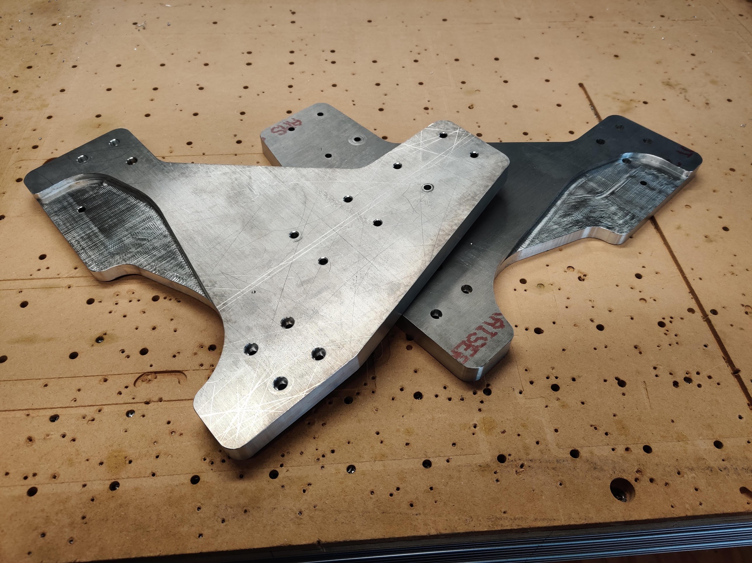
$180 cost of aluminum, 6 hours of machining/setup = $600 worth of parts if I was selling it.
-
08-11-2019, 10:39 PM #53
Member
- Join Date
- Apr 2016
- Posts
- 841
Re: CRP4896 Standard to Linear Rail Conversion
Originally Posted by nlancaster
Nice job! Your plates look a lot different than Avid's. Looks like there isn't going to be a lot of room for the head of the screw that attaches to the linear rail bearing block - the one in the pocket. Maybe it's just the camera angle. Are your plates thicker than Avid's, hence the pocket? Will probably make more sense when post pictures of them mounted.
Jeez, but aluminum sure is expensive.
Gary
-
08-11-2019, 10:43 PM #54
Member
- Join Date
- Feb 2005
- Posts
- 829
Re: CRP4896 Standard to Linear Rail Conversion
So my plates are 3/4 and so are Avids. I went with a pocket for the stepper drive system instead of a pocket for the linear carriage mounts.
The linear carriage bolt holes are 1mm oversize, and the head pocket is 1mm oversize. Should be plenty of room.
If you compare my design above to avids you will see that I reversed the aluminum extrusion to the inside of the plates, because my bed is already 57inches wide, the regular pro machine bed is only 50inches(aproximatly) wide.
-
08-12-2019, 01:01 AM #55
Member
- Join Date
- Apr 2016
- Posts
- 841
Re: CRP4896 Standard to Linear Rail Conversion
Originally Posted by nlancaster
I came to the conclusion that you reversed the pocket. The linear rail blocks wouldn't mount otherwise. All the bolt holes looked properly sized, however, the hole in the pocket looked like it was too close to the edge of the pocket. I know you would have avoided an issue like that. The camera angle was deceiving.
Makes sense why you reversed the pocket.
Gary
-
09-03-2019, 02:04 AM #56
Member
- Join Date
- Feb 2005
- Posts
- 829
Re: CRP4896 Standard to Linear Rail Conversion
Been working too much, Got back to this today.
Tapped 39 holes today.....
23 1/4-20
10 5/16-18
6 3/8-16
Used a tapping press and managed to not break any taps!!!
-
09-09-2019, 12:45 AM #57
Member
- Join Date
- Feb 2005
- Posts
- 829
Re: CRP4896 Standard to Linear Rail Conversion
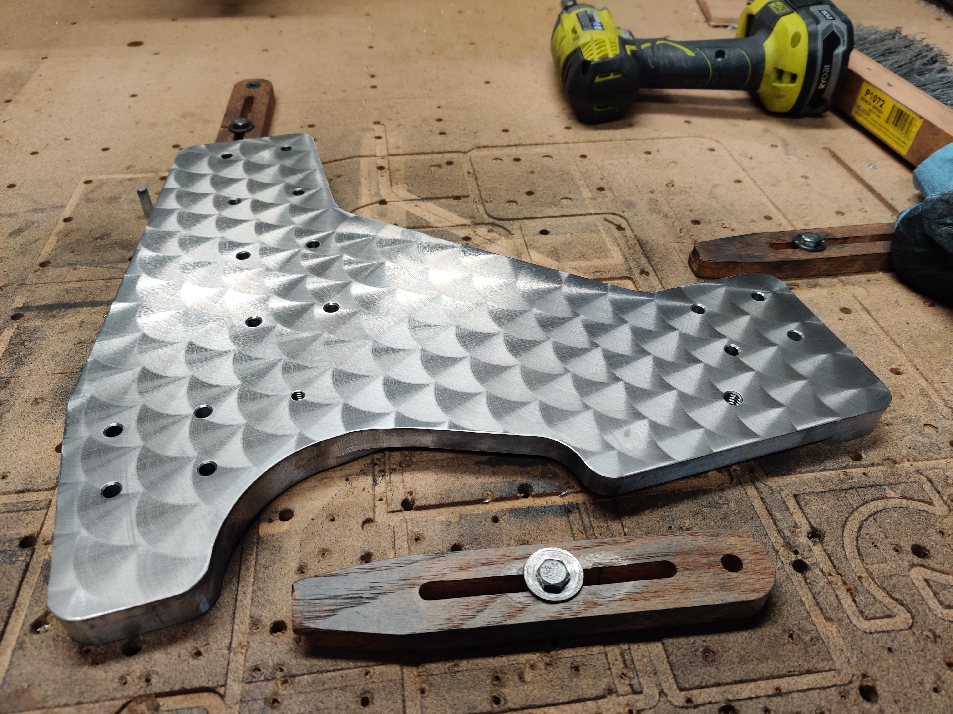
Engine turning all the conversion parts before I get them anodized.
-
09-09-2019, 02:07 AM #58
Registered


- Join Date
- Jan 2007
- Posts
- 626
Re: CRP4896 Standard to Linear Rail Conversion
Very nice!
How did you achieve that effect?
Will it will show through the anodizing?
-
09-09-2019, 05:25 AM #59
Member
- Join Date
- Feb 2005
- Posts
- 829
Re: CRP4896 Standard to Linear Rail Conversion
It should show thru anodizing just fine, as anodizing just changes the surface to aluminum oxide and introduces color to the process at the same moment.
I did it with a fine roll lock pad in my spindle, 8000rpm .075 step down to compress the roll lock pad, 1/2 second dwell time
Here is a video.
https://youtu.be/u0rVwpg0HFA
-
09-09-2019, 05:52 AM #60
Registered
- Join Date
- Jan 2015
- Posts
- 194
Re: CRP4896 Standard to Linear Rail Conversion
So very cool! Thank you for sharing!

 Reply With Quote
Similar Threads
-
HF 8x14 linear rail conversion....and maybe more...
By CS900 in forum Mini LatheReplies: 99Last Post: 08-10-2022, 02:12 PM -
Standard linear motion conversion to linear rails.
By bobmagnuson in forum Avid CNCReplies: 11Last Post: 03-25-2022, 09:52 PM -
G0704 Linear Rail Conversion
By BTP in forum Benchtop MachinesReplies: 63Last Post: 07-14-2019, 01:59 AM -
Sieg X3/SX3 Linear rail conversion
By DvG4 in forum Benchtop MachinesReplies: 1Last Post: 01-16-2011, 02:17 AM -
Mixing Preloaded&Standard linear trucks on same rail -pros and cons ?
By isvflorin in forum Linear and Rotary MotionReplies: 2Last Post: 01-13-2009, 06:05 PM
