


ok i have read as much as i can make sense of but for the life of me can not get it going.
i just got a AXBB-E and switched to uccnc from mach3 , i had it running via the rs485 plugin
but now this board allows me to control it properly so wanting to utilise the functions.
people keep referring read the manual but that was specific for the J1000 which has
different terminal connections also people keep saying look at the manual and see the relay
but there is no relay shown in the document other than the one feeding the limit switches .
so i realise i need to pickup the 5v - and they connect to the acm - dcm and also that the
A01 connects to the vi on the Huanyang VFD and i have switched the jumper over on the vfd.
so now hopeing some one has it up and running and can help by filling in the blanks for me.
Thread: axbb-e with Huanyang VFD
Results 1 to 20 of 33
-
09-20-2020, 11:05 PM #1
 Member
- Join Date
- Sep 2019
- Posts
- 9
axbb-e with Huanyang VFD
-
09-21-2020, 11:18 PM #2
Member
- Join Date
- Jan 2005
- Posts
- 15362
Re: axbb-e with Huanyang VFD
If you are using the RS485 connection you should stay with that for your speed control Originally Posted by fandtm666

For safety you can use a Relay for the For or FWD and DCM connection you need a relay on your AXBB-E to do this, this is just a switch there is no voltage to the For and DCM requiredMactec54
-
09-22-2020, 02:18 AM #3
Member
- Join Date
- Sep 2019
- Posts
- 9
Re: axbb-e with Huanyang VFD
thanks was hopeing it would be a simple connection .
-
09-23-2020, 12:11 PM #4
Member
- Join Date
- Sep 2019
- Posts
- 9
Re: axbb-e with Huanyang VFD
finally got it going no relay needed
removed jumper then
A01 = VI
ACM = 5V0
DCM = 24V0
FOR = pin 7 port 1
REV = pin 8 port 1
pid001 on vfd = 1
pid002 on vfd = 1
-
09-23-2020, 03:41 PM #5
Member
- Join Date
- Jan 2005
- Posts
- 15362
Re: axbb-e with Huanyang VFD
Yes you can do it that way By using active High or active low most VFD Drive can be controlled like this, but it is no a safe way of controlling the spindle On/off, that is why I don't recommend doing it that way Originally Posted by fandtm666
Mactec54
-
09-23-2020, 06:35 PM #6
Member
- Join Date
- Sep 2019
- Posts
- 9
Re: axbb-e with Huanyang VFD
im just following what the connection recommendations from
the manual for the axbb-e have shown.

-
09-30-2020, 03:19 PM #7
Registered
- Join Date
- Mar 2007
- Posts
- 18
Re: axbb-e with Huanyang VFD
Hi @fandtm666 - I'm also trying to get my Huanyang inverter working with an AXBB-E - Previously it was working with a chinese controller, but I need to run probe g-codes that it doesn't support, so I've been trying to upgrade to the axbb. I have it hooked up as you have now - but I've got problems - I'm worried that in my journey I've broken my inverter and that it's damaging my axbb. Originally Posted by fandtm666
With the inverter powered but nothing plugged into the inputs - I'm reading 24V on the FOR pin against DCM - see image. That seems very wrong to me - I don't suppose you could check your FOR voltage? no need to unplug anything - just see what the voltage is when the spindle is running and when it's not running.
thanks,
Kevin.
-
10-01-2020, 06:06 AM #8
Member
- Join Date
- Sep 2019
- Posts
- 9
Re: axbb-e with Huanyang VFD
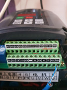
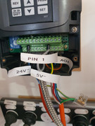
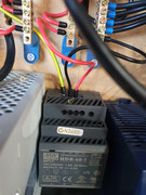
here are some pictures on mine setup look at the wire colours to help
its a bit of a mess only temporary while waiting for the new shielded cables to turn up


and a video
https://streamable.com/kiykp3
-
10-01-2020, 08:00 AM #9
Member
- Join Date
- Sep 2019
- Posts
- 9
Re: axbb-e with Huanyang VFD
also if you are concerned about the voltage you could hook up a relay
so your dcm and FOR connections to input of relay and then use you 5v
supply to feed so the 5v+ to the relay 5V- to dcm and relay output to FOR.
i just tested that and it worked.
-
10-01-2020, 09:16 AM #10
Registered
- Join Date
- Mar 2007
- Posts
- 18
Re: axbb-e with Huanyang VFD
thanks @fantm666 - one of the moderators here explained the 24V on the VFD inputs so I'm all good now.
Awesome setup by the way.
One more question - your "finally got it working" post says you removed the jumper - by which I assume you meant the jumper on the AXBB-E board controlling the voltage range?
On my board and running Mach3 the documentation is wrong. The PDF says "If the jumper is removed then the range is 0-10V" - but in my case removing the jumper limited the voltage range on A01 to 5V, I had to disassemble my setup and put the jumper back in to get 10V.
Are you driving your VFD with 10V or 5V?
thanks,
Kevin.
-
10-02-2020, 04:17 AM #11
Member
- Join Date
- Sep 2019
- Posts
- 9
Re: axbb-e with Huanyang VFD
just checked on mine and i actually put it back on so yep different to what
the manual says but works perfectly .
worked by removeing the pin as per manual but mine worked
as it should reading the rpm with the pin left in place and setting
Pid70 on the vfd to ( 0 )
A01 = VI
ACM = 5V0
DCM = 24V0
FOR = pin 7 port 1
REV = pin 8 port 1
pid001 on vfd = 1
pid002 on vfd = 1
cheers
-
10-02-2020, 03:54 PM #12
Community Moderator
- Join Date
- Dec 2003
- Posts
- 24220
Re: axbb-e with Huanyang VFD
Also as per the Manual, it shows how to use a separately supplied output from one of the isolated outputs direct to a opto isolated input such as the FOR/REV inputs of the VFD. No need for relay. Originally Posted by fandtm666
In this case the VFD supplies the DC source internally. The board has a open collector device.
This is explained in 9.1.2. page 21/29 etc. fig 9.2 explains it, just you do not need the 24v source.
The JPG show a similar method I use on G540.
Al.CNC, Mechatronics Integration and Custom Machine Design
“Logic will get you from A to B. Imagination will take you everywhere.”
Albert E.
-
10-02-2020, 05:32 PM #13
Community Moderator
- Join Date
- Dec 2003
- Posts
- 24220
Re: axbb-e with Huanyang VFD
More info on Sink/Source I/O
Al.CNC, Mechatronics Integration and Custom Machine Design
“Logic will get you from A to B. Imagination will take you everywhere.”
Albert E.
-
10-02-2020, 06:29 PM #14
Member
- Join Date
- Jan 2005
- Posts
- 15362
Re: axbb-e with Huanyang VFD
For safety it is a requirement to use a Relay, this is written in some better quality VFD manuals Originally Posted by Al_The_Man
This is safe for turning on a Pump / Fan Etc. but not a CNC Spindle that does manual tool changesMactec54
-
10-02-2020, 08:00 PM #15
Community Moderator
- Join Date
- Dec 2003
- Posts
- 24220
Re: axbb-e with Huanyang VFD
I have used some very high end VFD's of various manufacturers in my time but never seen any reference to it.
Many of these manufacturers also sell PLC and other interfaces, In the VFD manuals and the PLC, they show how to connect their open collector PLC etc outputs to the VFD.
The manual tool change instances generally have a brake, often to allow a tool check lock/unlock mechanism.
One of the Main units I have always used is Mitsubishi and they also refer to this method.
The bottom line is if concerned, ensure some kind of brake or electrical lock-out can be fitted.
My philosophy has always KISS (keep it simple) if possible.CNC, Mechatronics Integration and Custom Machine Design
“Logic will get you from A to B. Imagination will take you everywhere.”
Albert E.
-
10-03-2020, 01:01 AM #16
Member
- Join Date
- Jan 2005
- Posts
- 15362
Re: axbb-e with Huanyang VFD
You are talking about and industrial installation not a Hobby install Originally Posted by Al_The_Man
You would have an almost imposable task to add a brake to a 400Hz 24,000RPM spindle these guys use, you could be held liable if someone's hands got cutup by a false startup which happens more often than you think, You need to add a disclaimer or you could be held liable
If you used a PLC that would obviously be safe but no one here are using a PLC to deem the connection safe
Yaskawa has in there warnings, but you should already know this as most VFD Drive manuals have this
Two-wire sequence
Should not be used where safety of attending personnel might be threatened by a
restart. This method is generally restricted to unattended fans & pumps, or where
another controller is entrusted with the decision to restartMactec54
-
10-03-2020, 03:36 PM #17
Community Moderator
- Join Date
- Dec 2003
- Posts
- 24220
Re: axbb-e with Huanyang VFD
By brake, I am referring to the spindle locks such as fitted to the XLO's and BP's etc, in order to tool change, it is very simple to allow this feature when retro-fitting by only allow the pneumatic brake/lock to come by using the VFD 'At Zero Speed' output as an interlock.
The PLC output is no different from the G540 or the AXBB-E and other BOB's they both have open collector solid state devices and the current required by the typical VFD is a mere 20ma to 40ma sink current.
As an Industrial retro-fitter I have to abide by NFPA79 in N.A. so I always have a contactor in the supply to the VFD as per the manuals.
This can be activated by the E-stop to achieve the category 0 or 1 disconnect function.
This E-stop can be used when the machine is a at rest and safety is required.
I have used this method for 40years now without any re-percussion's or machine problems.
For safety reasons the DIY installation should be no different IMO.
Incidentally there are Mitsubishi models that have an enhanced version of this that allows main power of the VFD to be disconnected but leaves the low voltage circuit control active, this allows for rapid resume of the VFD once the main HV supply power is re-engaged.
Without going through the normal power up diagnostic sequence.CNC, Mechatronics Integration and Custom Machine Design
“Logic will get you from A to B. Imagination will take you everywhere.”
Albert E.
-
10-03-2020, 04:31 PM #18
Member
- Join Date
- Jan 2005
- Posts
- 15362
Re: axbb-e with Huanyang VFD
But the DIY installations are very different and you should know that with your 40 years of experience Originally Posted by Al_The_Man
Very few of these DIY builder's are using such machines, that all ready have spindle locks so there is no safety protection in place to protect there hands when changing tools, many have complained of false starts and have posted about this here on the Zone
No PLC's have many safe guards to prevent a false signal, you should know that, these controls do not, most have a safety Charge Pump but 99% do not incorporate into there system this would protect them but the way these systems are installed they are not safe without a Relay between the Control and the VFD Drive, no one ever gets a false start when a Relay is in place no matter how bad there system is put together
You can not turn a VFD Drive Off every time you need to change tools, you should know that, what you do and what these hobby guys do is totally different most don't have a contactor in place, so your 40 years of experience does not apply to what these guy do, you need to look at the whole picture of how there systems are put together then come up with a solution to make them safe
If the system has an ATC then the operator is not involved in changing the tools by hand so then you can wire as you have posted I do this all the time myself when the system is automated there is no personal safety problem to worry about
You have to separate the Industry from the DIY / Hobby both should comply and have the same standards, but they don't and you have no control over thatMactec54
-
10-03-2020, 04:48 PM #19
Community Moderator
- Join Date
- Dec 2003
- Posts
- 24220
Re: axbb-e with Huanyang VFD
This is why I stress that safety is a responsibility of DIY builder as well as everyone else, it is only forums such as this that can point the person who's level of expertise is not normally in this field.
There is nothing to stop anyone performing unsafe practices, but safety should be a subject of discussion, no different than any other machine building practice, there is at least on copy of NFPA79 out there in PDF, so it cost nothing to look over recommended practices and required regulations.
After being a member of this forum for 17yrs, I have always pointed out ways of conforming to safety requirements, no different from other typical Mechanical/Electrical helps and hints and should IMO, be part of it!.
Hopefully this is what the typical neophyte CNC machine tool builder will take away from forums such as this.
AlCNC, Mechatronics Integration and Custom Machine Design
“Logic will get you from A to B. Imagination will take you everywhere.”
Albert E.
-
10-03-2020, 07:58 PM #20
Member
- Join Date
- Sep 2019
- Posts
- 9
Re: axbb-e with Huanyang VFD
there has been some interesting comments and reasons for safety
mentioned and thanks to all for the points made.
i just want to say that when my machine is not working i always
activate my Estop and it is only deactivated when i am about to
start some work.

 Reply With Quote
Similar Threads
-
UCCNC & AXBB-E combo
By peteeng in forum Australia, New Zealand Club HouseReplies: 4Last Post: 06-02-2020, 01:14 PM -
New build using AXBB-e and huanyang vfd
By Chmexdf5633 in forum Spindles / VFDReplies: 4Last Post: 04-14-2020, 01:42 AM -
Its Aliveeeee my AXBB-E is working
By curiosity22 in forum Australia, New Zealand Club HouseReplies: 16Last Post: 01-31-2020, 01:39 AM -
my AXBB-E and UCSB are on the way, small annoyance is anyone using axbb with mach3?
By curiosity22 in forum Australia, New Zealand Club HouseReplies: 11Last Post: 05-17-2019, 03:50 AM -
New AXBB controller
By ger21 in forum UCCNC Control SoftwareReplies: 37Last Post: 03-20-2019, 11:55 PM
