


Considering the use of refractory around the crucible a fairly key point is efficiency in reducing radiant heat loss. This is proportional to the fourth power of the temperature (Stefan-Boltzmann law). Assuming the aim is to melt metal the losses due to radiant heating are likely to be much more than those due to coupling with thing other than the charge.
Another of the reasons why induction melting doesn't scale down very well.
Thread: Induction furnace
Results 121 to 140 of 305
-
04-30-2007, 10:33 AM #121
 Registered
- Join Date
- Apr 2004
- Posts
- 11
-
05-05-2007, 12:26 PM #122
Registered
- Join Date
- Mar 2007
- Posts
- 85
An interesting point there jc.
All the castable refractory I have seen has been a white colour, which should reflect radiant heat energy fairly well back into the melt, even if the refractory itself does not get that hot. I am guessing it should all still scale down, particularly if a higher operating frequency is selected.
I now have a working oil pump, which is a typical vane type power steering pump running at 950 Rpm. This pumps just under a gallon a minute of automatic transmission fluid (mineral oil), and almost fully loads the 1/2 hp drive motor. The next step in all this will be to assemble all the components of the 15Kw dc power supply, and the oil cooling system onto a large piece of reinforced 3mm aluminium sheet.
-
05-23-2007, 03:08 PM #123
Registered
- Join Date
- Apr 2007
- Posts
- 13
Been gone for a while
Well people, I've been traveling around for a while and honestly forgot to check back on this thread for over a month.
Warpspeed - can you give us an update on your progress?
BTW, I would just stick with water or water/glycol mix for the cooling medium. Use a refractory cast coil to keep the molten metal off the coil.
Just my humble opinion.
97T - so, you've peaked my curiosity. We've met a couple of times, the induction industry is like living in a small town, everyone knows, or knows of everyone else. Drop me a pm.
-
05-23-2007, 11:38 PM #124
Registered
- Join Date
- Mar 2007
- Posts
- 85
Shawn, progress has been slowed by having to repair some major car engine problems, and various other annoying little distractions. But I am now firmly back on track.
Before I could really begin assembling anything, I needed to get and test all the larger and more important parts to figure out how it was all going to go together. That stage has only now been reached, and just yesterday I welded up a steel angle frame.
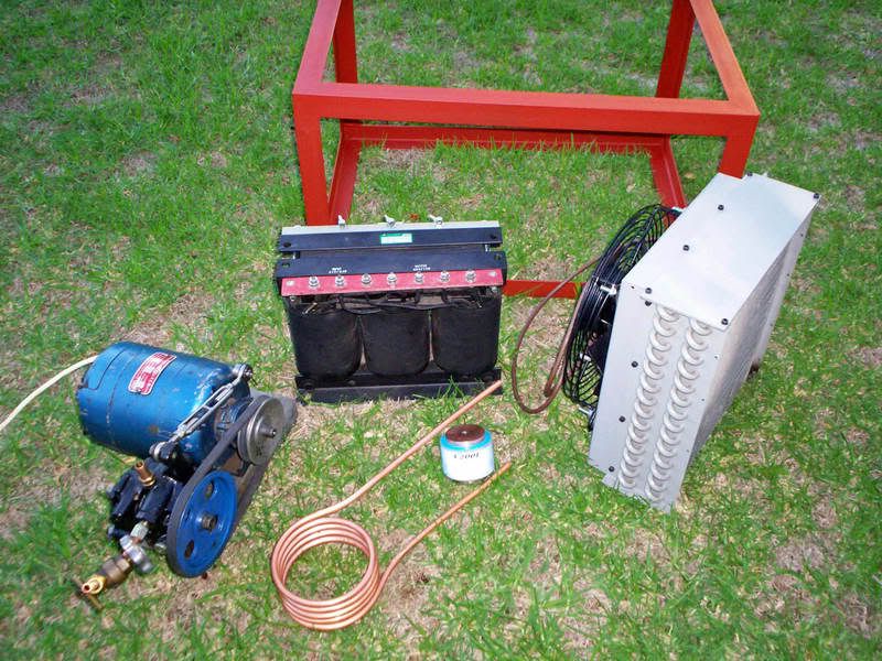
Here are the major parts. A 15Kva transformer, one gallon per minute oil pump, fan coil unit, and the all important 20Khz tank components. The steel frame has just been painted with zinc chromate primer only hours ago, and is not yet properly dry.
-
05-24-2007, 12:13 AM #125
Registered
- Join Date
- Jan 2006
- Posts
- 481
Hi
I will give you credit guys , some very impressive ideas and working induction furnaces.
Dammmmmmmmmm i need more hours in a day and a extra set of hands .
Seems i have to stick to my LPgas fired furnace for now
keep up the good work guys
cheers
-
06-05-2007, 06:11 AM #126
Registered
- Join Date
- Mar 2007
- Posts
- 85
O/k guys, further update on progress.
I now have all the heavy low tech and not very interesting "life support system" components mounted into the main frame, and on wheels.
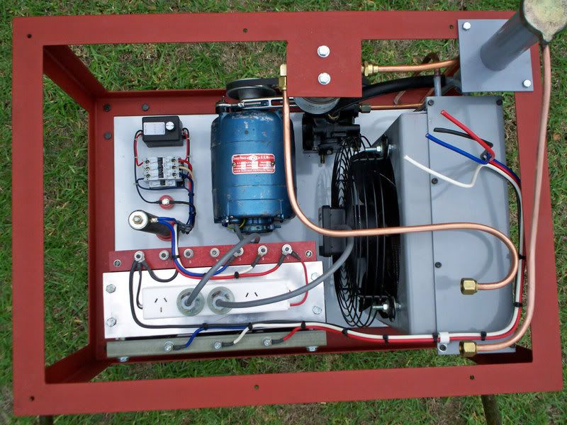
The electrical system comprises a three phase auto transformer, 240v 20Amps per phase in, 175v 27 Amps per phase out continuously rated. It has a 100 ohm 225 watt soft starting resistor in one phase only, operated from a 0-5sec time delay relay and contactor.
I still have to provide a 20Amp three phase circuit breaker and an ac ammeter. These will be mounted on the outer sheet metal covers that will probably be about the last thing to be done.
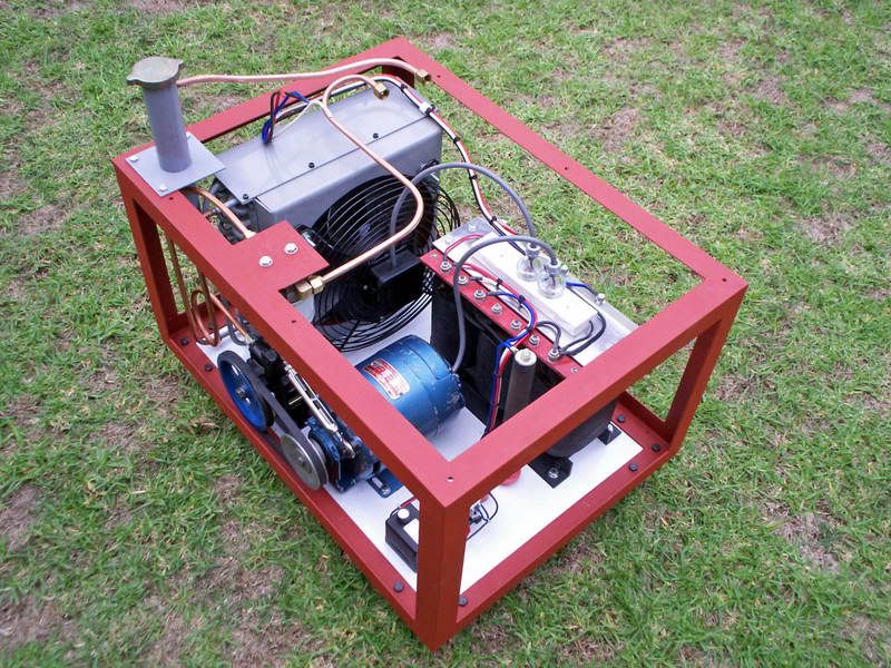
The oil cooling system part of it is now complete. It consists of the tall grey neck, which is an air separator and reservoir for the hot return oil. It holds one litre when half full. This feeds the Toyota power steering pump driven at 950 rpm with a half horse motor. The oil then flows through the fan coil unit fitted with a 1,200 cfm fan. Actual measured airflow is around 850 cfm. Oil from the fan coil unit then goes through a small automotive oil filter.
All of the more interesting stuff will be mounted onto a single large flat 3mm aluminium plate. This plate will bolt on top of the frame with the six mounting holes visible in the picture. This plate will be readily removable from the top of the main frame for convenience. Oil and power connections to the main electronics will be arranged to be very easily and quickly disconnected.
Now all the big heavy stuff is completed, I can concentrate on the more interesting electronics fitted onto this aluminium top plate. The next thing to do, will be building the rectifiers and dc power supplies.
-
06-05-2007, 02:11 PM #127
Gold Member
- Join Date
- Jul 2005
- Posts
- 12177
You do realise that real backyard boffin would have tacked everything together with baling wire and sellotape. That looks far too professional
 .
An open mind is a virtue...so long as all the common sense has not leaked out.
.
An open mind is a virtue...so long as all the common sense has not leaked out.
-
06-05-2007, 04:27 PM #128
Registered
- Join Date
- Apr 2007
- Posts
- 13
I agree. I don't think I've ever assembled anything at home that looks as nice as your project Warpspeed. Good work. :wave: Originally Posted by Geof

-
06-16-2007, 01:53 AM #129
Registered
- Join Date
- Mar 2007
- Posts
- 85
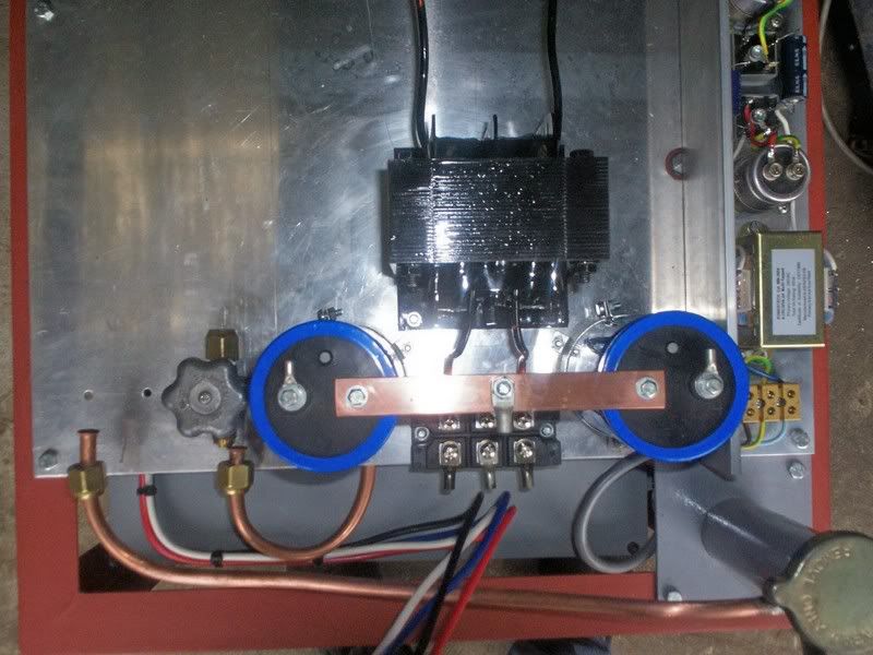
Rectifiers and filter capacitors have been fitted to the top deck plate, easy and there is not much really to show. The common mode choke for the three phase rectifier, is also now complete and bolted down.
Next job on the list is the 4mH 35 amp high frequency inductor for the buck regulator, mainly because it will be so large that other components will need to fit in around it. Planning this has been a fairly frustrating exercise.
My first approach was to use four great slabs of powdered iron arranged in a rectangle, and the ideal material to use would be the Fluxtrol flux concentrating material sometimes used with induction heaters. That idea rapidly died when I received a quote of $1,800 dollars for four pieces considerably smaller than I required.
Attempt number two was a redesign using a stack of the largest powdered iron toroids available. Something around five inches in diameter and six inches tall would have been about right, requiring around 250 turns. The only cores available ex stock were of a completely unsuitable material. Being toroids there is no air gap to adjust. What you buy is what you get and impossible to do anything with if it does not work out as expected. I was quoted FOUR MONTHS delivery on suitable cores. So that idea was shelved.
The other problem with toroids is the difficulty of winding, especially something on this large a scale, so I went back to the patient and long suffering powdered iron core sales rep, and inquired about the largest available powdered iron E cores. He never even bothered to get back to me.
That left ferrite cores as a possibility. Ferrite is less desirable because it saturates at only around a quarter of the flux density of powdered iron, and it is far more expensive. Anyhow I scrounged eight sets of large UI cores that will do the job, and as they were free, the price was right. Just as well because new ones would have cost me $480.
The C coress shown in the lower right of the picture were what I intended to use originally when I was thinking in terms of 5KW maximum power. This whole project has now morphed into 15+ KW thinking, so the eight sets of UI cores will be what I will be usinge. There is 9Kg of ferrite there !
-
06-17-2007, 03:02 AM #130
Registered
- Join Date
- Jan 2006
- Posts
- 481
hi Warpspeed
I must commend you on a very professional undertaking in a electric furnace . Ideal one just flicks a ON/OFF switch and away you melt.
Very expensive to man this electric furnace and probably beyond the average backyard hobbyist.
That's why i chose my trust LPgas fired furnace , i experiment with a few different size LPgas torches and wooooooooooo some of the heat i can put out is enormous. It is clean burning and works great to and cheap to make and run also.
The main reasons i built a LPgas fired furnace is cause i get old discarded LPgas tanks form fitters around my area for nothing and generally there well over hal full of LPgas. Scrap metal yards will not take LPgas tanks for scrap unless there completely empty and all the valving removed . Otherwise there is a dangerous element that they could have a LPGas explosions in there scrap metal facility while processing the scrap metal.
Here in Australia the LPgas units fitted to vehicles and machinery have to be inspected every ten years the gas storage tanks. Some gas tanks are not re-used as to have a inspection done and the tank brought upto todays standards exceeds the cost of a new tank , so alot of old tanks are just pulled out and thrown away.
My LPgas torches , some times i use to 2 inch torches to melt large sums of metal quickly and when i have both or even one running on over 30psi LPgas pressure they sound like jet fighter planes flying over my workshop. When i run them on around 5 psi Lpgas pressure they just sound nice .
I modelled my torch of this website
http://members.optusnet.com.au/terrybrown/welcome.html
http://members.optusnet.com.au/terry...PGasTorch.html
http://home.earthlink.net/~jschwytze...e_furnace.html
http://www.nhsouth.com/crafts/workbench/lptorch.htm
http://www.backyardmetalcasting.com/refractories.html
The flame is over a meter long and about 15 to 20 cm wide in a section , looks awesome at night starts.
It took me a while to get the jetting right for the correct burn ratio of the flame , it is colorless and odorless the burning flame. No external fans required to aid in additional air for the flame.
Like i said it sounds awesome when one cranks up the gas pressure
I melt 10 to 20 kilos of aluminum in anyone pour a very quick time once i have heated up the furnace.
I am in the process of gathering materials for a bigger furnace build so i can melt larger quantities of metal. one 25 kg Blast Furnace Refractory cement is $55 per bag and i need 30 bags
This is a awesome build can't wait to see it in action though.
Warpspeed , keep up the good work.
-
06-17-2007, 04:13 AM #131
Registered
- Join Date
- Mar 2007
- Posts
- 85
Propane works very well for melting aluminium, and with a well designed burner and furnace, copper and bronze too. But melting iron or steel is just not going to happen with a basic propane fired furnace.
Even with a flame a hundred feet long, the temperature is just not there. Gas welding steel with a propane/air burner is just not possible.
Natural gas is just as good as propane, and only a fraction of the cost, at least in Australia it is. To tune your burner, try hooking up an automotive exhaust oxygen sensor. It will give a very sensitive indication of correct stoichiometric air/gas ratio and maximum peak flame temperature.
A decent sized induction furnace is certainly not a low cost beginners project, that's for sure. I don't even know if this is going to work. The internet is littered with failed induction furnace projects where people have given up trying to reach decent power levels. But I am willing to give this a try, no matter how it eventually turns out.
-
06-17-2007, 08:50 AM #132
Registered
- Join Date
- May 2004
- Posts
- 402
Warpspeed, whereas I largely agree with you that propane is not the way to go for melting iron and especially steel, in fact you can (and I have) melted iron in a propane pit furnace. The flame temperature is infact high enough but getting the concentration of energy into the required target is very difficult. This results in enormously long melt times and cold pours.
The reason I got my induction furnace was that I had to down grade from a diesel fired Morgan Crucibal No5 (1/3rd megawatt and a bit smelly!) to a propane fired Kasenite pit furnace when my neighbour built a house 10 foot from my foundry and I was reduced to the lower melting point metals.Andrew Mawson
East Sussex, UK
-
06-18-2007, 12:53 AM #133
Registered
- Join Date
- Mar 2007
- Posts
- 85
Yes Andrew I agree. An ordinary propane air burner will only just exceeds iron melting temperature by a very small margin, and to do it, it needs really good flame control and excellent furnace insulation. But it would be extremely slow, rather costly in fuel, and very energy inefficient.
The problem is the 80% inert nitrogen content in the air which does nothing but chill the flame. There are two different solutions to that problem. The first is displace some of that nitrogen with extra introduced oxygen, but that would make a decent sized home furnace hopelessly expensive to run.
Another better approach is to preheat the burner air somehow, so the nitrogen going into the burner also gets heated. Flame temperature rises almost exactly by the amount of burner air preheat added, and the whole process can be made extremely efficient.
The traditional and very ancient method of melting iron is to blow air through a bed of burning coke or charcoal. Combustion is not all in one place, but as the air passes through the glowing bed of coals it gains temperature. That is the principle behind the blast furnace or cupola. Another neater way to do it with a gas burner, is to just use a flue gas heat recovery system.
I tried this myself with a very small experimental natural gas fired furnace, and it was successful enough to encourage me to start constructing a more serious and better engineered natural gas iron melting furnace with a flue gas heat exchanger.
The only complication I encountered was that as the burner air is preheated it expands very significantly. 300C of preheat (or more) drops the air density down to half (or less), and that can do terrible things to the burner air/gas ratio as everything heats up. The air blower needs to be made variable, and an automatic adjustment of blower speed can be arranged by using an automotive exhaust oxygen sensor in the flue gas, and a closed loop feedback system to control the air blower. I have had all this working in prototype form, and it was most encouraging.
That project is now on hold, but will be resurrected if this induction furnace project strikes any really serious snags.
The induction furnace design is a challenge which I find fascinating, and if it works, it might give others a few ideas to build upon. But if it falls in a heap, plan B will be to go back to the natural gas fired heat recovery furnace.
-
06-18-2007, 02:30 PM #134
Registered
- Join Date
- Jun 2007
- Posts
- 23
Hehe, I think most hobbyists tend to run out of resources, either money or time. I made an induction heater a while ago, got it working up at 2kW and melted a 20c coin (non ferrous). It was operating at somewhere around 210kHz. Ended up running out of mosfets, and running out of time Originally Posted by Warpspeed
 My mum wasn't too impressed by the accidental burns on the carpet either >_<
Wilson
-
06-18-2007, 02:38 PM #135
Gold Member
- Join Date
- Dec 2004
- Posts
- 524
(quoting from: http://www.abana.org/ronreil/theforge3.html)
ABANA sells plans for a regenerative gas forge designed by Robb Gunter et al at Sandia. The updated plans are available through ABANA. Call the office at 314-390-2133, 9 - 5 CST.
KenKenneth Lerman
55 Main Street
Newtown, CT 06470
-
06-19-2007, 08:32 AM #136
Registered
- Join Date
- Mar 2007
- Posts
- 85
Further update on the induction heater project.
I now have the ferrite cores for the buck regulator choke, so the next task is to cut my roll of bulk .005" copper foil into 35mm strips so that it can be wound onto these cores. My bulk roll is 300mm wide and was discovered to be 29 metres long. One layer of foil that wide should be able to carry twelve amps with acceptable current density and temperature rise, so I will require three layers of foil per turn to carry the required 35 amps.
Some mathematical gymnastics suggest I require to cut six rolls of foil 35mm wide and 29 metres long to suitably fill the window area in the cores with copper. All I can say is, cutting 175 metres of this foil accurately with a pair of scissors was a fairly extreme exercise in patience and persistence.
The next step required a fairly important design decision, which I am still not entirely sure of. There are two possible design choices.
I could assume that this is a high powered 40 Khz ac inductor, and that some serious skin effects in the foils would require that each foil needs to be insulated from the other foils, to prevent significant overheating under power. Each turn in effect becomes three entirely independent insulated foil windings connected in parallel. That would be the safe option, but it requires three layers of insulation which leaves considerably less room for copper.
A bolder assumption would be that this is really a dc choke, with only a small superimposed high frequency ripple current. The MMF required at 40 Khz to sustain the 440 volt peak to peak square wave buck regulator drive waveform is really quite low, provided I can fit sufficient turns onto the core. So that is the choice I made. If proved wrong I can unwind the foils, and rewind it with extra layers of insulation without too much drama. Later on, testing will determine if I have made a wise or a foolish choice.
So here we go, three .005 foils wound together as one .015 foil with just one layer of mylar insulation. Hopefully this will allow more turns to fit on the cores, and a higher ratio of copper to insulation.
The eight cores have been epoxied together, and epoxied onto a steel base plate, which is bolted to the faceplate of my lathe. The lathe is in lowest gear and only turned by hand. It is really just a fairly rigid rotating vise that allows me to really put some winding tension on the foils to flatten out any wrinkles.
When I came to epoxy all the cores together, the surfaces were all over the place. The specified dimensions were +/- 1mm, and so I had to grind the cores to get everything reasonably even. That is why they have a blotchy appearance. But apart from a few really ugly chips, these free secondhand recovered cores should work fine. Once the whole thing has had the air gaps set, and been tested and proven it will be dipped and baked with proper transformer varnish. That should cover up a lot of the ugliness, and nobody will ever know.
-
06-19-2007, 09:26 AM #137
Registered
- Join Date
- May 2004
- Posts
- 402
I bet your fingers are sore after all that scissor use! There is a simple device intended for trimming a fixed width strip off the edge of a roll of wallpaper, that uses a pair of wheels as a rotary shear to give a clean cut, and has an adjustable fence to set the width - I think I'd have made something like that to cut that copper. As for inter layer insulation, I would have been tempted to chemically oxidise the copper. The oxide layer would have been quite adequate between your three trifilar conductors, still using the mylar as you have done between turns.
AWEMAndrew Mawson
East Sussex, UK
-
06-19-2007, 10:29 AM #138
Registered
- Join Date
- Mar 2007
- Posts
- 85
Ha-ha, yes, it was rather an ordeal Andrew. More mental than physical. I did consider buying a guillotine especially for this, but thought it might be rater difficult passing the foil past the hinge without deforming the edge. One thing is for sure, those scissors are no longer the scissors they once were after cutting up all that copper.
I did construct a scribing jig to give me an accurate line to cut to. Commercial splitting of foil is also available, but I am retired, and am too mean, and too poor to pay someone else to do it. And paying someone else to do your hobby for you goes against the ethic.
Anyhow, some sort of suffering is all part of most really worthwhile projects. But I am now really glad that part of it is now over!!
-
06-20-2007, 12:16 AM #139
Registered
- Join Date
- Jan 2006
- Posts
- 481
hi
Warpspeed , that is certainly a great effort in cutting well over 170 meters of copper foil.
Once the bug bites , there is no turning back.
keep up the good work , would love to see you succeed in this project.
cheers
-
06-24-2007, 12:34 AM #140
Registered
- Join Date
- Mar 2007
- Posts
- 85
Once my choke was wound, testing showed that I had at least one shorted turn, and some significant electrical leakage resistance down to the ferrite. Not very good. Although extreme care was taken during winding, the foils must have slipped sideways during tensioning.
Fortunately I had decided to fit two hemispherical hardwood blocks at the ends of the core. This makes the inner windings a very smooth oval shape, not rectangular. The foil is not creased as it would otherwise be where it would have passed over the sharp corners of the ferrite. This enables the foil to be pulled very tight after being wound, by allowing the turns to slip slightly over each other. But most importantly it meant that the foil can be unwound without being damaged by having creases at the corners.
The three layers of foil were then bound together spiral fashion with 35mm wide .002" mylar insulation, allowing plenty of overlap. The foil turns were replaced onto the core without any further problems.
I managed to fit on 68 turns until the foil became level with the top of the ferrite. This used up about 3/4 of the foil I had cut. Inductance without the I cores fitted was just over 3mH, and fitting the I cores required a 12mm airgap to reach the design 4mH. My original estimate of required airgap was 10mm, so it is very pleasing to see the calculated figures appear pretty much spot on. Dc resistance measured at 75 milliohms, and I meggered the winding to core at 1,000v dc to get a reading so high as to be unmeasurable.
The 75 milliohms will give a copper loss of around 92W at 35 amps which is not much for such a large component. All things considered a very satisfactory outcome. I cannot do any further testing with this until I have some of the electronics going, but at least it is now together and I know exactly how large it is going to end up. Quite a monster, 9Kg of ferrite, and 13Kg all up.
The next task will be to fabricate six oil cooled heatsinks, now that I know how much space is available.

 Reply With Quote
Similar Threads
-
12.5 kW Induction Furnace
By meanu in forum Casting MetalsReplies: 1Last Post: 04-24-2013, 07:19 AM -
My Furnace
By vertek in forum Casting MetalsReplies: 6Last Post: 02-28-2008, 07:15 AM -
induction furnace
By vallabesan in forum CNC Machine Related ElectronicsReplies: 5Last Post: 12-13-2007, 04:19 AM -
Arc Furnace
By aggie_67 in forum Casting MetalsReplies: 4Last Post: 08-28-2007, 06:27 AM -
DIY Oil Furnace
By aggie_67 in forum Casting MetalsReplies: 9Last Post: 09-24-2006, 02:35 PM
