


I've been reading this, and im impressed at every ones work, im still wondering in which area i should go but the cheapest by far is a simple propane furnace
I'm only 18 /19. so im young enough, I am learning alot from everyone, which i would assume is the idea.
Its a pitty that I live in Ireland in a way but hey.
all the best to everyone and I hope you all continue to make, experiment and
design things so i can learn more.
Seb.
Thread: Induction furnace
Results 141 to 160 of 305
-
06-24-2007, 01:30 AM #141
 Registered
- Join Date
- May 2007
- Posts
- 5
-
07-02-2007, 11:09 AM #142
Registered
- Join Date
- Jun 2007
- Posts
- 1
I read all the post since the beginning i i think that there will be anyone here who can help me.
I've finished the refurbishment of an older balzers induction furnace. The furnace has a close chamber where the coil is. I'm melting titanium on it in vacuum but I pretend to have an argon atmosphere inside.
I'm doing vacuum inside the camera until 1x10⁻¹ mbar and them i fill it with argon until 800 mbar. With these conditions i turn on the power unit( an old calamari of 10kw from 1980-in fact i don't know the frequency neither the voltage or current in the coil and Calamari neither) and i see an electric arc between the two feeding tubes of the coil.
The strange is that if i increase the pressure from the 800 mbar to 850mbar with air the electric arc disappear and i can melt the metal without any problem.
Anybody can help me?
Bruno
-
07-02-2007, 11:27 AM #143
Registered
- Join Date
- May 2004
- Posts
- 402
Warpspeed, sorry to hear that you had to re-wind. Two steps forwards and one back! When I was an impecunious student very many year ago (1965) I wanted to make a high power power supply, but couldn't afford the heavy copper wire to wind the transformer. I then found that the local (long now gone!) ironmonger had coils of bare copper wire in sizes of just over 1/8" at affordable prices. I strung lengths of it up in our cellar, and gave it all three coats of brushed on clear polyurathene varnish and left it several days to go really hard. In trepidation I wound on the secondary, assembled the laminations and tried it. Frankly to my surprise it worked, and carried on working for at least 15 years until I passed it on to someone else. It always smelled vaguely varnishy when heavily loaded <G>
AWEMAndrew Mawson
East Sussex, UK
-
07-03-2007, 01:09 AM #144
Registered
- Join Date
- Mar 2007
- Posts
- 85
Bruno,
What you are doing is completely outside my area of experience and knowledge, sorry.
Andrew,
That transformer winding experience of yours, certainly strikes a chord with me !! Some of my more youthful experiments were less successful than yours.
Heatsink fabrication is progressing rather slowly, and with a slight change of plan. My original testing was with a prototype water cooled heatsink that passed a hundred watts through five square inches of wetted surface. It was the copper/water interface that was the greatest heat barrier, and five square inches would have just worked, but more exposed wetted area would have been much better.
My decision to go to oil cooling has made things rather more difficult.The specific heat of oil is only about 0.6 that of water, but I fixed that by more than doubling the coolant flow rate. The other problem is that thermal conductivity of the oil is only around a quarter that of water, so I will require at least twenty square inches of wetted surface to transfer the "nominal" design hundred watts dissipation per heatsink.
There are six heatsinks, and the physical area available to mount them, limits their size. After several attempts at silver soldering some copper pipe directly to these heatsinks I have abandoned that approach as being quite impractical. I simply cannot find a simple neat way to get enough wetted surface area in such a small space.
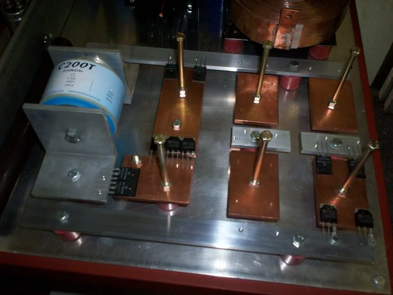
So the plan now is to just attatch my semiconductors onto quarter inch slabs of copper, and than bolt a suitable oil cooled heat exchanger onto the same copper plate. I can then experiment with different designs of bolt on heat exchanger fairly simply.
So that is where I am right now. I have the power semiconductors laid out on what is virtually a giant circuit board with quarter inch thick tracks, this fills the available space. The removable heat exchanger cooling system will be bolted on top of each heatsink with long bolts seen in the picture.
I still need to drill and tap many holes, and there is still plenty to do, but here is a mock up of where I am at the moment. The buck regulator with its bypass capacitor are at the left, and the H bridge is located at the right.
-
07-03-2007, 01:20 AM #145
Registered
- Join Date
- Jun 2006
- Posts
- 6
Hi Warpspeed
I am currently designing a IGBT based Brushless DC Motor controller that is good for 400A at 300V for an electric vehicle as my final year thesis project in a Bachelor of Electrical and Electronic Engineering. I am interested in what looks like copper plated bolts in your last picture.
Where you able to source these from within Australia? If so where?
They would be better for bolting down the terminals on my IGBT modules than the unplated steel ones I'm using at the moment.
Great work on the induction heater.
Cheers,
Andy.
-
07-03-2007, 08:07 PM #146
Registered
- Join Date
- May 2004
- Posts
- 402
Warpspeed, I am suprised that you are having dificulties silver soldering tube directly to your heatsinks as it should go very nicely if you have the right (quite large) heat source. Oxy-acetylene would be my first choice, followed by air-propane with a big burner.
I would recommend that you investigate 'phoson' brazing rod as used in the heating and ventilation trades for brazing copper pipe joints. It works well and requires no flux for copper to copper joints, flows nicely and makes nice neat fillets:
http://tinyurl.com/2ybozz
I used it on the 3/4" water & 3 kHz power feed pipes to my 100kW furnace and it was completely sucessful. (I used Oxy-acetylene). I also used it on some of the brass fittings I had to make up, but for brass you need a borax based flux.
I'm sure brazing coolant pipes directly to your copper slabs is the way to go to extract the most heat. You can zig-zag the pipes to increase the contact area.
AWEMAndrew Mawson
East Sussex, UK
-
07-04-2007, 01:44 AM #147
Registered
- Join Date
- Mar 2007
- Posts
- 85
Wow Rambo, that motor controller project sounds like a real beast. Alas, they are not copper bolts but merely ordinary cheapy 6mm mild steel bolts that just happened to have that "gold" passivated plated finish. A trick of the light I am afraid.
Andrew, the very least of my problems was the silver soldering ! My cooling circuit all uses 3/8 diameter pipe, which needs to be quite long to get enough surface area for each heatsink. That requires that it be folded or coiled as these heatsinks are only two inches by three inches in total area. There are really two fundamental problems, getting acute enough bends in the pipe, and dodging all the screws, bolts, and main threaded insulators with my pipe. I did fabricate a serpantine monstrosity, but the pipe lenth was really too short to be truly effective as a heat exchanger. And it was ugly as sin and very tricky to fabricate.
There seem to be two obvious approaches to this. Bolt some sort of tall thermally conductive pillar to the top of the heatsink, and wind a coil of 3/8 copper pipe around that, secured with silver solder. The thing can be made fairly tall and could fit on many turns, so the pipe length could end up being made surprisingly long. I had thought of turning up a soild aluminium central core, press fitted or tightly shrunk into an outer copper sleeve with the cooling pipe wound on top of that. Fairly simple.
Another way would be a tight cluster of seven copper tubes (like boiler tubes) arranged to provide wetted fins inside a copper cylinder. That would be neater and more compact, and a bit more complicated to make. But it could have the convenience of having both the oil inlet and oil outlet ports both located at the top, and it would be much slimmer than the coiled copper pipe idea. That would allow far more access room around my semiconductors, they would be burried beneath a coiled pipe which needs to be given a reasonable turn radius to get sufficient length.
But a bolted on, oil cooled heat absorber has another big advantage. All six heat absorbers can be quickly unbolted from their respective heatsinks, and the whole electronic assembly removed to be worked upon without having to break into the oil circulating circuit. Once I get this thing leak free, I don't want to have a flood of spilt oil over everything every time I need to remove the electronic chassis away from the very heavy and bulky main frame. So the bolted down heat absorbers have a long term practical value, as well as being easier to make.
I am having diabolical computer trouble at the moment, so have been diverted away from all this. But not for very long I hope.
-
07-04-2007, 06:54 PM #148
Registered
- Join Date
- May 2004
- Posts
- 402
Warpspeed, THIS is how you should insulate that choke:
http://www.zen40166.zen.co.uk/image005.jpg
http://www.zen40166.zen.co.uk/image006.jpg
http://www.zen40166.zen.co.uk/image007.jpg
<GGGG>
AWEMAndrew Mawson
East Sussex, UK
-
07-04-2007, 10:32 PM #149
Community Moderator


- Join Date
- Mar 2004
- Posts
- 1661
Well, at least he made his own welder, did you?.. *Laugh out VERY loud* Originally Posted by awemawson


-
07-04-2007, 11:06 PM #150
Registered
- Join Date
- May 2004
- Posts
- 402
Well actually YES for my first welder! It was in 1968, I had an Austin Healey Frog Eyed Sprite with a rusted out floor. Got the works metal bashers to bend up a new section in exchange for a packet of fags. Bought the biggest scrap transformer I could find in our 'recycling' place for 10 shillings. Cut off the original secondary, and wound on a new secondary out of very heavy earth cable. Scrounged some welding rods from the place my flatmate worked (local power station) and 'had at it'. It wasn't pretty but it passed it's MOT test. I used the same 'welder' to weld the main chassis member of my late brothers MG TC. Deep v'ed the crack and made a very good structural weld which lasted to my knowledge for twenty years. That welder later got put in a box which was oil filled, and was equipped with secondary taps for voltage selection with rather smart brass taper sockets. I sold it after a couple of years and bought a cheap Italian import, which I still have for emergancy use when I'm desperate <G> Originally Posted by svenakela
(so there !!!!!)
AWEMAndrew Mawson
East Sussex, UK
-
07-05-2007, 03:03 AM #151
Registered
- Join Date
- Mar 2007
- Posts
- 85
Great pictures Andrew !! To get the full effect, he should really be welding in bare feet.
I have just e-mailed those pictures to two really good friends, each is an electrical engineer that owns and runs his own transformer winding business. I am sure it will add significantly to their many decades of knowledge and experience in the transformer winding industry.
HA-ha-ha-ha-ha, good one Andrew, still wiping the tears from my eyes.
-
07-16-2007, 02:35 PM #152
Registered
- Join Date
- Apr 2004
- Posts
- 11
For cooling the latest computer overclocking stuff may be of interest:
http://www.theinquirer.net/default.aspx?article=40993
-
07-17-2007, 01:36 AM #153
Registered
- Join Date
- Mar 2007
- Posts
- 85
Still not out of the woods with the cooling system yet, but at least the end this part of the project is now in sight.
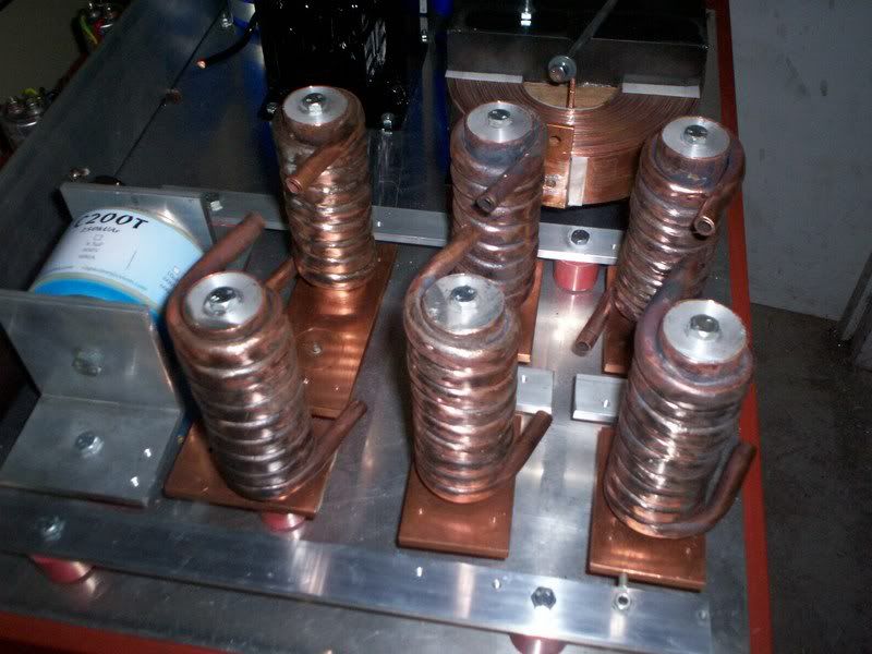
I have now fabricated six heat exchanger coils for the six heatsinks. These consist of four feet of 3/8 copper pipe wound around a 1.25 inch copper tube and silver soldered, giving eight and a half turns, plus short tails. The inside of this 1.25 inch copper tube was filled with molten aluminium to form a solid central thermally conductive core. The copper shrunk over the aluminium while cooling, producing a really tight fit.
These heatsinks are only 120mm tall and fairly compact, but they provide approximately 45 square inches of wetted surface area. No proper thermal tests have been carried out yet , but some initial early trials with water cooling suggested that five square inches of wetted area with water would be marginal for a hundred watts. I now have nine times that, so expect it should work pretty well, even with oil.
-
07-19-2007, 05:50 PM #154
Registered
- Join Date
- Jul 2006
- Posts
- 4
wow .... Amazing
I think this thread go to be more Confusing
But we are hobbiest ,nut Competents.
we need a small and simple induction furnace
which we can make it at backyard with affordable
stuff.
if .....Impossible .... OK
what about resistance furnace.
I think ,we can reach up to 1500 C
is it right?
-
07-23-2007, 06:34 AM #155
Registered
- Join Date
- Mar 2007
- Posts
- 85
Yes this project is definitely over engineered, but I want to build something that will be powerful, reliable, and trouble free at the first attempt. So I would rather proceed slowly, than have to completely rebuild it several times.
The dc power supply and the cooling system are fundamental requirements. Definitely not a particularly high tech part of the design, but still an absolutely necessary foundation onto which the success of the much more interesting electronics will depend.
With any high power, high frequency circuit, layout and thermal management vital parts of the design. The schematic circuit and the components are only half of it. How it actually goes together physically plays an important part in how reliably it will be, and how well it will work. So a lot of thought needs to go into how the parts actually fit together physically, not just what parts to use.
I know all this is painfully slow, but I am using this project to fill in spare time. It is not an urgent priority job with a deadline for completion. But I am learning as I go, and at best, others may benefit from some of my crazy ideas, or at worst avoid some of the problems or disasters I may create for myself.
I am especially grateful to have other posters here in this thread that know far more about all this than I do.
-
07-23-2007, 09:22 AM #156
Community Moderator
- Join Date
- Mar 2004
- Posts
- 1661
I like this project, totally nuts!

What is the budget on the electronics?
-
07-25-2007, 07:04 PM #157
Registered
- Join Date
- Dec 2005
- Posts
- 430
mmmmmm power
awesome
-
08-04-2007, 11:01 AM #158
Registered
- Join Date
- Mar 2007
- Posts
- 85
I have never really thought about that. Originally Posted by svenakela
The all up cost (I hope) should not be that horrendous, because I am using mostly secondhand and scrounged parts, or parts that I already have. It is a bit of a Frankenstein monster in many respects. But, for instance, saying that I used a five dollar secondhand Toyota oil pump, or something I found while dumpster diving behind a factory, is probably not a realistic way to cost this whole project out. I am trying to do all this as cheaply as possible without cutting too many corners on specifications. It would be just about impossible to duplicate it exactly the way it is, even by me!
But the idea is to establish some sort of initial design requirement, and figure out ways to solve problems as they arise. A bit further down the track when I begin testing the true electronics design part of it, I can be a lot more specific.
One major design decision I made early, was to use individual low cost plastic diodes and IGBTs in TO247 packages, bolted directly (uninsulated) to electrically isolated individual copper heatsinks. A very wide choice of various high performance devices are available at very reasonable cost, especially with 600 volt ratings.
An alternative would have been a single huge flat air cooled finned aluminium heatsink, with bolted on commercial modules. Suitable modules are vastly more expensive, and there is not a very wide choice of really high performance devices available. Price and delivery can be ridiculous for some of these modules.
I would much rather blow up four common $13.00 IGBTs than four $185.00 IGBT modules!!! As there are going to be at least eleven power devices, that saving should really add up. (one IGBT and one diode in the buck regulator) (four IGBTs and four diodes in the bridge) (plus one over voltage clamping diode for the big choke).
All this has added much more mechanical complexity and work, especially the oil cooling of the individual heatsinks, and is taking much longer to assemble. But it sure should save me some serious money doing it that way in the long run, especially if I start blowing up a significant number of devices later on.
It also means I can test at low power with a minimum number of low cost devices to prove my design, monitor waveforms and so on. When it finally looks like working, I can parallel up additional power devices to multiply the power. This is not usually possible with modules that already have multiple devices inside. So for R&D, it is far preferable.
I have not been very forthcoming with exact details, costs and so on. That will come later once there is more of it assembled and there is something actually up and working, and some definite results to show.
-
08-20-2007, 07:44 PM #159
Registered
- Join Date
- Aug 2007
- Posts
- 2
smaller melts
Please look at this
http://www.rdoinduction.com/images/S...th-RCS-RDO.pdf
their supercast 3 would do what I want...but $28k would not LOL
so I am wondering....could a high voltage tunable power supply like
http://cgi.ebay.com/ws/eBayISAPI.dll...m=170140311977
outputting to an array of IGBTs.....driven by a frequency generator like
http://cgi.ebay.com/ws/eBayISAPI.dll...m=120152441260
work to drive a simularly sized coil?
If not why not?
-
08-20-2007, 11:15 PM #160
Gold Member
- Join Date
- Dec 2004
- Posts
- 524
NO. That power supply will supply only 15ma. That's 30 watts. The function generator does not seem to be able to track the resonant frequency of the tank circuit. Originally Posted by metalations
You could perhaps demonstrate the basic idea at low power using these components, but there is no way to use them in a production circuit.
KenKenneth Lerman
55 Main Street
Newtown, CT 06470

 Reply With Quote
Similar Threads
-
12.5 kW Induction Furnace
By meanu in forum Casting MetalsReplies: 1Last Post: 04-24-2013, 07:19 AM -
My Furnace
By vertek in forum Casting MetalsReplies: 6Last Post: 02-28-2008, 07:15 AM -
induction furnace
By vallabesan in forum CNC Machine Related ElectronicsReplies: 5Last Post: 12-13-2007, 04:19 AM -
Arc Furnace
By aggie_67 in forum Casting MetalsReplies: 4Last Post: 08-28-2007, 06:27 AM -
DIY Oil Furnace
By aggie_67 in forum Casting MetalsReplies: 9Last Post: 09-24-2006, 02:35 PM
