


What about your step pulse frequency? you using a very low count encoder? Mach3 can only do 45000 pulses/sec. Just curious.
Thanks for the info.
Thread: 5axis router plasma 10'x5'x24"
Results 21 to 36 of 36
-
09-30-2010, 08:32 PM #21
 Registered

- Join Date
- Oct 2007
- Posts
- 123
-
09-30-2010, 08:36 PM #22
Registered
- Join Date
- Oct 2007
- Posts
- 123
latest . . . working on electronics enclosures, switch brackets & enclosures, etc. More later.
Sorry about the double post, laptop issues.
-
09-30-2010, 08:56 PM #23
Registered
- Join Date
- Aug 2008
- Posts
- 1166
Smooth stepper can let it output a higher pulse rate, or iiirc the Granite Device drives I plan on using can multiply the number of step pulses. My encoders are in the 2000 pulse / rev range.
CNC mill build thread: http://www.cnczone.com/forums/vertical_mill_lathe_project_log/110305-gantry_mill.html
-
10-09-2010, 05:12 AM #24
Registered
- Join Date
- Oct 2007
- Posts
- 123
Here's the solution for the gearing/torque at the spindle tip. I came up with a double belt drive reduction using 5mmHTD belts and pulleys from Sdp-si.com and from bbman.com. The final drive ratio is 20.57:1 and I'm using an RS34-1290 stepper from HomeshopCNC on both the A & C axes. The stepper uses 8amps at 1290oz-in, the Gecko203V will let 7.8amps through wide open, so that gives me 1257oz-in at the motor and about 135# to push the tool through the material assuming I have a 12" lever arm from the tool tip to the center-line of the A axis. That's assuming a 4" stick-out of say a 1/2" end mill, but likely it will be less than that most of the time. With a 20% safety factor, I've got about 108# to push the tool. At that kind of pressure, the tip will be deflecting too much for a finish cut anyway so I think I should be safe with that design. The shafts for the belt reduction pulleys have to be made in house, the pulleys are also machined and modified to come up with the solutions for the setup. Nearly back together, a couple more days on it & the A/C should be at final assembly. Then back to the electronics enclosures & wiring, switches etc.
-
10-15-2010, 05:51 AM #25
Registered
- Join Date
- Oct 2007
- Posts
- 123
I completed the gear reductions for the A & C axis. Here's a youtube vid:
YouTube - calvinoArchitect's Channel
The 1290's from homeshopcnc will work great. There's a pretty big resistance with just the belts tensioned & motors not even powered on. You can turn it by hand, but you have to put quite a bit of pressure to turn either axis.
The Spindle drawing called out an ER25 collet, I ordered a collet wrench, but it did not fit, plus I still did not have the wrench to hold the shaft, so I just drew up the collet & shaft wrenches & cut them from 3/16" plate, ground the end for a close fit & it works great. Anyone know about ER25 collets? Is there a large & small version? Here's a vid summary of that:
YouTube - calvinoArchitect's Channel
Working on the enclosures & layout of the electronics at the moment. Anyone have any good suggestions for plugs for the motor wires? There must be a male/female connector with strain relief out there somewhere, I'm just not finding it at the moment.
Well, :cheers: . . . Forge ahead
-
10-30-2010, 09:20 PM #26
Registered
- Join Date
- Oct 2007
- Posts
- 123
Paint time, then wire it up.
:cheers:
-
12-04-2010, 05:40 AM #27
Registered
- Join Date
- Oct 2007
- Posts
- 123
2010-11-05
Final Assembly after paint.
Gantry re-assembled, all bolts get thread lock, either chemical ("Locktite" or similar) or lockwashers depending on location.
Cooling system for Spindle. Re-designed to shorten the run of 3/8" rubber hose - original design had nearly 100' or hose which produced a resistance of around 20psi - would require a huge pump. Relocated entire system to the back side of the Y gantry so coolant hose run is less than 20' requiring only approx. 4psi. Run with a 12v pump producing ~330gph, a 2.5qt reservoir, a small aluminum radiator with two 4-11/16", 12Vdc electronic fans. Final flow should be approx 1.3gpm (5lpm).
Wiring and electronics. The control cabinet is completed, it is electrically isolated from the table by (4) nylon disc spacers at the top 4 corners. This is to keep any hi freq. noise from crossing from the plasma or VFD into the control electronics. The Plasma unit sits on a shelf next to the selector switch - select between plasma and spindle. The electroncs enclosure is filled with 5 power supplies (3 for motors, a 24V for the cabinet cooling fans & the Z-axis power-off brake & its time delay relay, plus a 12V supply for the cooling system pump & fans). The power in is 50 amp, 240V with a neutral leg so I can pull 120V to power the computer & monitor + the CandCNC MP3000E CNC controller.
The floating Z head (works like this: [nomedia="http://www.youtube.com/watch?v=an5HYBQWTpg"]YouTube - CNC plasma with THC and floating head switch[/nomedia] ) is mounted via four(4) 5/16NC18 studs on the back side of the spindle mount cage & has a standby mount above the C axis on the Z carriage.
Limit switches (MPJA - Power Supply, Power Supplies, Security Cameras, LCD, Fans, Etc.) are located at the + & - extremes of each axis & will trip the machine into E-stop if activated. This should prevent lost steps in the event of a crash into hard stops.
E-stop buttons (4) (The best way to buy industrial controls--low prices, fast shipping and superior service.) are located at each corner of the machine and stop all actions including g-code on the machine.
Home switches are located on each axis: at 60" on X, 0" on Y, Z is only used in plasma & is floating in order to locate surface of metal, at 0deg. on A, & 0deg. on C axis. The locations of these can be specified in Mach3.
Next post should include initial tests of plasma & spindle for operation & initial axis motion!
:cheers:
-Mike
-
12-14-2010, 11:54 PM #28
Registered
- Join Date
- Oct 2007
- Posts
- 123
Initial 5 axis motion.
YouTube - calvinoArchitect's Channel
YouTube - calvinoArchitect's Channel
In progress, more to come.
Cheers!
-
12-18-2010, 02:54 PM #29
Registered
- Join Date
- Feb 2009
- Posts
- 227
Mike,
I have been following your build with great interest and your machine is awesome. CNC builds take forever but once things start moving it is all worth it... Good Luck with everything and keep us updated...
-
12-18-2010, 03:57 PM #30
Registered
- Join Date
- Oct 2006
- Posts
- 30
Impressive build. Any examples of what you plan on cutting utilizing all 5 axis'?
-
12-31-2010, 05:04 AM #31
Registered
- Join Date
- Oct 2007
- Posts
- 123
Yea Dustin, everything takes a little longer than you think, but I was pretty close on this one. I actually did this one for The Fay Jones School of Architecture at University of Arkansas. So I have to truck it up there now and give it to them . . . of course with a proper demonstration and breaking in party. I'm sure plenty of students will have some pretty sweet ideas & concepts to develop on it over the years.
As for me, I almost have all of the parts to make my 4'x10'x20": machine a 5 axis, & I'll make the time to get it there.
Jeep07:, I have some forms that I want to carve with it to start with . . . it's a concept really about creating a structural system and getting a light quality into a space & use the form to regulate heat gain and dissipation. I'm thinking forms for either fiberglass or concrete panels. I have another idea for using stamped or formed sheetmetal which would be plasma cut to create a sort of honeycomb panel which would be "perforated" similar to these openings.
A couple of these screen shots show a parametric definition created in Grasshopper for Rhino3d which allows me to control and change the amplitude & period of the sine curve that created the opening between panels. The idea is that the panel is 2'x4' or 4'x8' etc. I then can export the surface to create the G-code with the CNCtoolKit.
It's really a next generation of this concept:
index
(it'll take a minute to load) but it's a similar concept using 20"dia. x 18"deep, angled sheet metal tubes made from cnc plasma cut, 20ga sheet - with round lenses in them, to light a space - the roof (upper & lower) in that structure has 46 of those skylights & they're angled to let in light at specific times of the day & year and let in more direct light in winter, less in summer to control heat gain.
It's a work in progress!
It'll be interesting to see what the students & faculty at Uark come up with to do with the machine at their facility.
Cheers!
-Mike
-
12-31-2010, 05:13 AM #32
Registered
- Join Date
- Oct 2007
- Posts
- 123
YouTube - Calvino 5 axis router test
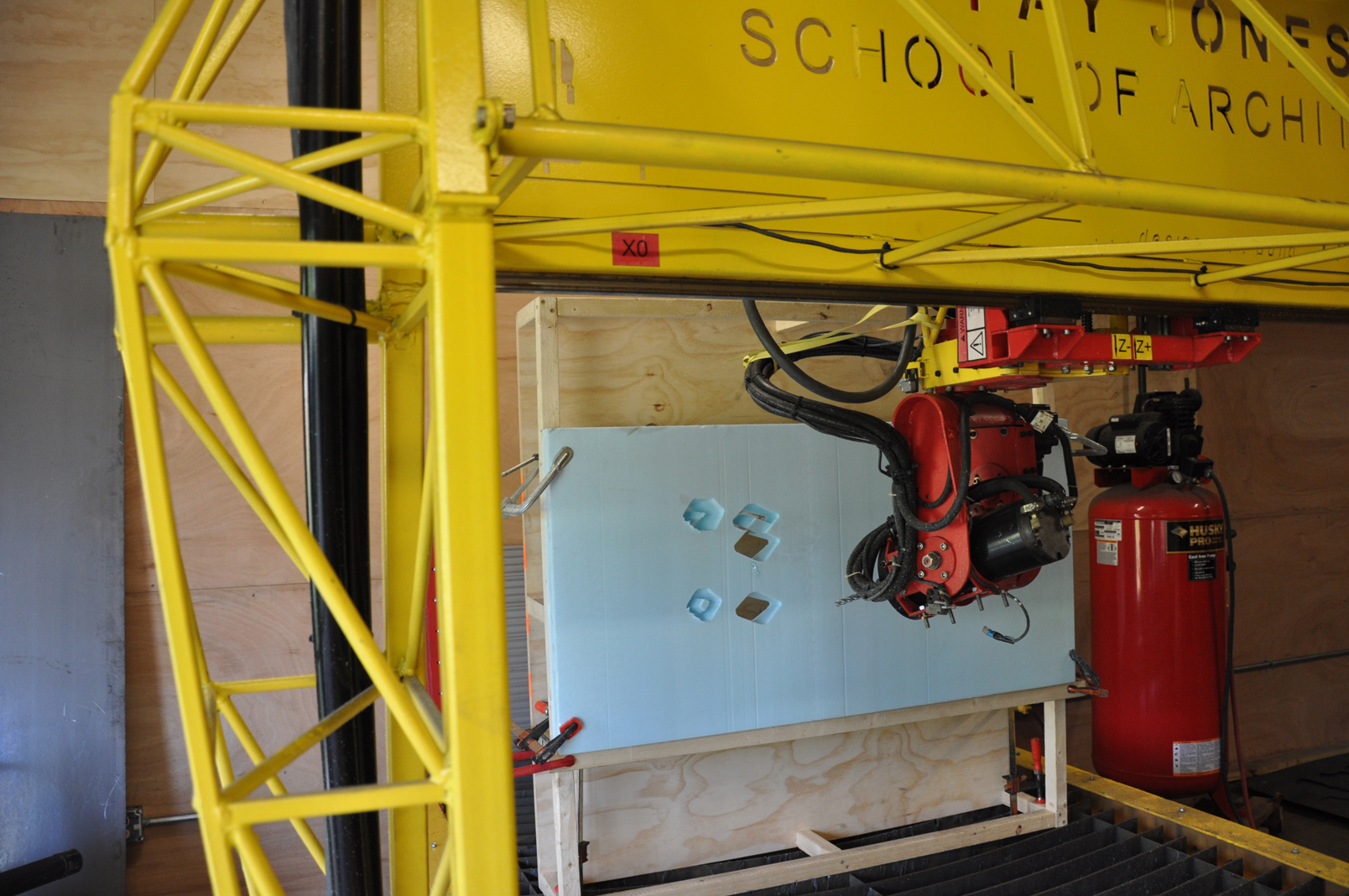
That's the latest test cut I was able to do with the Uark 5 axis. Unfortunately I will not be able to do much more 5 axis code & testing with the forms concept because I have to load up the machine & take it to Arkansas. This is a scaled down foam form. The g-code generation still has a few bugs to work out, but it's getting there.
YouTube - calvinoArchitect's Channel
A few other vids in there of setting up/testing the plasma/router.
Cheers!
:cheers:
--Mike
-
02-25-2011, 11:51 PM #33
Registered
- Join Date
- Oct 2007
- Posts
- 123
I'm planning to release the plans for this machine (with a few, small modifications) as an open source set through Kickstarter if the funding goal is reached, check out the link:
Open Source 5 axis CNC Router & Plasma Machine Plans 5'x10' by Mike Calvino — Kickstarter
The plans will include 3d cad models, some 2d cad drawings, some cut files, parts lists, and suppliers lists. If the funding goal is reached, the documents for the instruction set will be available as an open source download from my website at
CalvinoCNC - 5 axis machine plans
Check out the Kickstarter bit & see if it interests you.
Cheers!
:cheers:
-
03-01-2011, 03:44 AM #34
Registered
- Join Date
- Oct 2007
- Posts
- 123
I just started another thread that will be just about the open source plan/instruction document set:
http://www.cnczone.com/forums/plasma...tml#post904400
Stay tuned there for updates about approx. material costs & other info.
:cheers:
-Calvino
-
03-01-2011, 03:52 AM #35
Registered
- Join Date
- Oct 2007
- Posts
- 123
Well, I also posted a thread in the DIY woodworking machines sections under open source cnc machine designs forum:
http://www.cnczone.com/forums/open_s...tml#post904405
:cheers:
-Calvino
-
06-30-2011, 04:50 AM #36
Registered
- Join Date
- Oct 2007
- Posts
- 123
Here's a link to the blog where updates are posted of what they're doing with the 5 axis machine: srpLAB
YouTube - ‪SRPLAB 5AxisSwarfing 01‬‏
YouTube - ‪FABCRAFT_STEEL PLASMA CUTTING.m4v‬‏
srpLAB » DSC_1110
Cheers!
-Calvino

 Reply With Quote
Similar Threads
-
"low end" HF Spindle or "high end" router for about $1000?
By biomed_eng in forum DIY CNC Router Table MachinesReplies: 14Last Post: 01-06-2012, 07:15 AM -
3 or 5axis Router Machine time in Perth, WA
By Sadara in forum Employment OpportunityReplies: 0Last Post: 07-19-2010, 06:26 AM -
Precision Plasma LLC 6" rotary chuck for CNC plasma cutting
By rchacich in forum News AnnouncementsReplies: 0Last Post: 05-26-2010, 06:57 PM
