


I can't be much help with your design questions, other than to say I might enlarge the spindle mounting arm and increase the height of the (red) mounting plate to space out the bearings a bit more and help with the torque on the spindle arm. Given that you'll be using fairly small sized tools with the 2.2kW spindle, maybe that isn't really an issue.
As far as servos go - like anything else they need to be matched to the application. They can absolutely be direct driven because they have very consistent torque over the RPM range. I direct drive on my wood router with 300W BLDC servos. Because servos tend to have a wide RPM range, people often gear them down to increase the mechanical advantage and use as much of that RPM range as possible.
What type of screws are you planning to use?
Steve
Results 1 to 12 of 12
Hybrid View
-
07-23-2011, 03:18 PM #1
 Registered
- Join Date
- Jan 2006
- Posts
- 628
-
07-23-2011, 10:01 PM #2
Registered
- Join Date
- Jun 2006
- Posts
- 82
wow man, thanks for the encouragement! buying a ready made mill is not an option as I want to build it so I can fix it when it brakes down! Originally Posted by digitalmdi

I have started but have struggled to confirm that my design is based on some good principles and that I have accounted for all of the major stresses/factors.
I had planned on beefing up that spindle mount, this was one of the last parts to be cut so had left the design until the casting of the base was well under way. I also planned to run more fast feeds with smaller cutters so was also feeling the same as you (little need for HUGE stiffness to combat HUGE cutters). I think i will also lean to swapping to the second design with smaller cutting space but far better spacing and to the eye a more balanced layout. I can't help but feel a cutting spaced longer than the spacing of the bearings will create points of flex or areas where leverage could affect my accuracy. Originally Posted by stevespo
Thanks for the info on the servos. I think I will play it safe and work in space to both direct drive or gear with a tooth pully and belt to give me options when i get to that upgrade.
I plan on using ballscrews from Linearmotion2008 on ebay. I have a stack of end mounts for 16mm screws so now just deciding between 5 or 10mm pitch
once again, thanks for all the feed back guys! Keep it coming!
-
07-26-2011, 06:26 PM #3
Registered
- Join Date
- Apr 2009
- Posts
- 43
[QUOTE=jestah;969609]wow man, thanks for the encouragement! buying a ready made mill is not an option as I want to build it so I can fix it when it brakes down!
Sorry to throw water on your fire, but as one who has "been there-done that" I can predict that at the very best, it will take you 6 months and many $ before you even make your first test cut. Then an equal amount of time refining it to a working unit. You could buy a Chinese mill, tear it down and re-assemble it the right way in a few weeks. Or just buy a Tormach and go to work. If this is just a hobby project to see if you can build something, then the time and $ are no problem.
-
07-26-2011, 10:31 PM #4
Registered
- Join Date
- Jun 2006
- Posts
- 82
[quote=digitalmdi;970599]
I have been well over 6 months, threeish years to date but have been given very clear end point. I am to far invested in the parts/stock i have and to be honest that is about 99% of the things I will need to finish the project. Originally Posted by jestah
I have just got back from the company I plan to use to cast my base and possibly column from epoxy. I just now have to double check with my resin guys if the rubber tuffened resin system I use will be ok in such a big mix (around 15-20L will be needed) and make a mould at work and I'm ready to cast.
Once the base is done I have an other cnc builder who is willing to then cut all the required mounting surfaces and do all the drilling and tapping.
The electronics are done and ready to be mounted so really starting to feel things are coming together well!
Don't worry about your comment, Think of it more like tossing water onto a boiling pot of oil! Gave me a nudge to prove you wrong!
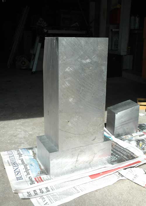
sorry there are not much photos yet guys, will make sure to take some when I am making the mould and while i am casting the base.
Big question now is my 6z rails. Could some one help me understand the bearing load rating chart and the numbers I can use to decide on my final spacing? I have a final reach of around 400mm and plan to use a small high speed spindle cutting small cuts fast in ally and hopefully some work in steel. I know in the drawing the stand off looks a little small but that is just a mock up to get spacing correct. I would like to now work on working out exact bearing spacing and stand off size to lock in the design .
thanks
jestah
-
07-27-2011, 02:43 PM #5
Registered
- Join Date
- Apr 2009
- Posts
- 43
[quote=jestah;970675]
Maybe I misread your post- I thought it was another of those Cad-Cam fantasies where they drone on for months and years with endless calculations about the distance to the moon divided by the square root of the universe. Looks like you are well into the project, with a definite plan in mind. Would like to see more pictures as you progress- the guy who built the slant bed lathe has a really good thread. Originally Posted by digitalmdi
Good luck

 Reply With Quote
Similar Threads
-
Need Advice on a Desktop Mill
By LatheMaster in forum Benchtop MachinesReplies: 7Last Post: 11-15-2010, 08:33 PM -
Getting Ready for Mill Delivery - Advice Appreciated
By webgeek in forum NovakonReplies: 4Last Post: 08-19-2010, 09:04 PM -
Considering a (first) machine build, a small desktop mill
By footloose in forum Open Source CNC Machine DesignsReplies: 6Last Post: 05-25-2010, 07:12 AM -
Small desktop gen-purpose CNC mill on a shoestring budget
By GreenLead in forum Benchtop MachinesReplies: 33Last Post: 09-15-2008, 03:03 AM
