


Hi Sky....LOL.....this making a machine to make a machine is like the movie about the rise of the robots.......once a robot became a bit intelligent it went on to create itself but with enhanced characteristics that in the end gave birth to the super Big Daddy robot.
I think you are right in the SVM-0 thinking in keeping it within the bounds of it's envelope without stressing the other factors that make it a precision mill.
For my interest point of view, I would keep the ER32 spindle as the main standard offering, and have options available for ISO20 and the 65mm diam 6,000 rpm engraving spindle with the whatever ER end, probably ER11, whatever.
If it's possible to gild the lily any further, I would opt for a double nut ballscrew on the X axis, (even though it does reduce the table travel by a smidgeon), as in this area more back and forth travel is performed with the longer travel distance and this can only increase the wear in the nut, whereas the Y axis only has a short travel, so not so much wear would be encountered.......the Z is the least wear prone, even though it has to bear the whole weight of the head with inertia loads, and as a gas strut takes care of the direct weight a single nut would suffice.
I think the enclosure could be an option too, but if it's successfully arrived at it would be a valuable asset to maintenance in the swarf area.
I think also if Mist cooling were to be the preferred coolant source, the enclosure could be sectionalised and user assembled from preformed jointed panels with Silicon to seal the joints......and lots of window area would make it light and visible to view the progress, as most of the users would not be so blasé when it comes to seeing the machine walk the talk etc, and would like to see it in operation, unless you were doing CNC for a full time occupation and only wanted to press the green button when the red light flashes.....LOL.....no fun in that.
A full enclosure would be nice, but I think it would be difficult to ship without the packing case becoming huge.
If a full enclosure is on the cards, then consideration must be taken for those that want to attempt to fit some form of power draw bar mechanism for QTC options, and that could be easy if a panel were removable or just cut out of the top of the cabinet, so no big drama there.
There should be adequate clearance in the door opening area, as a too cramped opening will make life hard......the distance between the outside of an average person's body with arms by their sides would be an indication of how much room is needed when you are half inside the enclosure changing cutters and setting up jobs etc.
That is why I was interested in the Levil LW400 enclosure system with the drop down front panel etc, although having a fully enclosed enclosure and the door sliding sideways off to the side would give plenty of access......no doubt you will surprise us with a cool design as usual.
Ian.
Results 401 to 420 of 3662
-
10-01-2013, 06:12 PM #401
 Member
- Join Date
- Sep 2006
- Posts
- 6463
-
10-01-2013, 06:32 PM #402
Member
- Join Date
- Sep 2006
- Posts
- 6463
Hi Sky, I posted the last post before seeing the very last post with the part finished enclosure etc.
What are the overall dimensions of the cabinet?
Ian.
-
10-01-2013, 07:01 PM #403
Registered

- Join Date
- Jul 2011
- Posts
- 441
Hi, The overall dimension is 1000*580*560mm WLH Originally Posted by handlewanker
 www.skyfirecnc.com
Email: [email protected]; Skype: skyfirecnc
-
10-01-2013, 07:27 PM #404
Registered
- Join Date
- Jul 2011
- Posts
- 441
You make me think of the TERMINATOR series movie now...

I think the ideas you mentioned about spindles is what I'm going to do..
I agree with your idea of double nut ballscrew for X axis.. I'm sure I will consider it carefully.
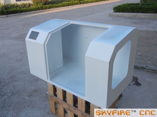
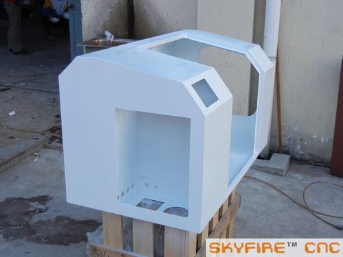
Actually my current enclosure maybe should call half enclosure.. I think it's enough and not need a big square enclosure to cover all of the machine height. It can not be said as a cool design.. but should be a good solution with a big clear window and front door. I will use PC glasses there. I placed the electric box inside the enclosure in a place that the wortable and work piece will never touch. This will save space and make the enclosure as compact as possible. And a LED work light will also be arranged inside.. The package size with the enclosure is not very big. I think should be about 1100*680*1000mm WLH. The standar SVM-0 without enclosure package will be 650*600*900mm. So the package ratio is 0.748m3 vs 0.351m3. I think it's not big deal about package under 1m3. At least it's not much different price of sea shipping...www.skyfirecnc.com
Email: [email protected]; Skype: skyfirecnc
-
10-02-2013, 04:34 AM #405
Member
- Join Date
- Sep 2006
- Posts
- 6463
Hi, that enclosure size is great, not too big but adequate......by partial enclosure I take it that the mill column would protrude out of the top of the casing about halfway, enough to still have the spindle end within the casing to keep swarf down......it mostly flies out sideways.
I don't think you can make an enclosure smaller than that for the SVM-0 size machine without cramping things, and the table has to have a clear run both ends anyway.
For shipping, would the mill be mounted in the enclosure as a complete entity and then boxed in a wooden crate?
That'd be interesting......all the optional "extras" for a package deal, like a 4th axis (100mm chuck?), a set of 10 tool holders (ISO20/ER32 chuck), 100mm mill vice, clamp set etc , could be contained in the package without incurring separate shipping costs if they were sourced individually on EBAY etc......that would be one sweet package.
On the topic of the mist coolant, not having used that type but know of it, would it be necessary to have compressed air for the propellant with coolant added to the air stream, so creating a latent heat type of cooling from the atomisation of the coolant liquid, or can you have the coolant propelled by a pump like an injector to create a mist but without the need of a compressor etc.
I have in mind the design of the hand operated liquid spray bottle that you can buy to spray liquids for garden and other uses etc, as this type of design does not use any pressure but only the pump action of the plunger on the liquid forcing it through a small nozzle to atomise it.
If this type of operation can be utilised for spraying coolant onto a cutter, do you think it will work as such or is an air stream also needed.
I see the commercial mist coolant systems all use the venturi principle where the coolant is sucked up and mixed with an air stream, but that means a compressor for the air supply and lots of noise etc......it would also depend on the amount of air needed to keep the cutter cool and misted with coolant.
If the direct injection type works it would be simple enough to have a small pump for the pressure and adjust the nozzle to control the flow and rate.
I might do some tests on my mill with a spray bottle to see if the cutter reacts favourably to it........at worst case, any coolant however small is better than no coolant, and I don't want to resort to a squeezy bottle splashing coolant now and then from a distance....LOL.
The other thing is swarf removal, which normally get hosed down from the cabinet walls with a coolant hose when full coolant flow is used, but I think a Shop Vac set-up will cover that problem as mist is the preferred method for the SVM-0.
The time is approaching when the cards must be laid on the table and serious negotiations for a package deal need doing.
On that aspect, what kind of lead time can we expect from an order placement to shipping date from your end?
I just thought up an idea to cut shipping costs........if the packing crate was made totally waterproof and a sail attached to it, you could launch the package from your nearest sea port and have a GPS guidance system to guide it to the port of destination.
For an express delivery a solar panel could drive a small electric motor and propeller to cut sailing time when the wind stopped blowing.....LOL........only joking, I didn't think it was a good idea either.....some pirates could hijack the package.
Ian.
-
10-02-2013, 06:09 AM #406
Registered
- Join Date
- Jul 2011
- Posts
- 441
Hi, yes. this is the most compact design for this enclosure we can have. Original design could be even shorter. But after Imade the longger X table and take AC servo motors in options. The enclosure height was carefully decided so the chips have very small chance to fly out the enclosure even the head at top position.
Yes. The SVM-0 will be mounted in the enclosure and fastened together with the enclosure and base mount bracket. Then the whole unit will be fastend to the wood case bottom via the base mount. Then we cover the machine with plastic bag and close the wood case. Any other accessories can be put inside the package to save shipping cost.
Ithink there are two methods to solve the mist coolant spring. One is to use a small air compressor. We know there are some slient type air compressor that normally used for tatoo.. I think should be usable to mist coolant too. It's small and cheap. about $50-$80 I guess.
Another method is something like the small electric sprayer that normally used for farm chemicals. A small diaphragm pump will solve the power issue. I’m sure this will work too. Maybe sometime I can do some tests. But must not as better as air flow mist. Because air flow will take heat away.
If the enclosure integrate the chip removal parts, it will have to be some larger size and may need the stand together..
For an order issue, I can promise a 25-30 day lead time to send out the SVM-0 if don’t have very special requests that need long time to gather parts.
Haha… very interesting… I guess the auto ocean shipping… not only the peoblem of hijack..Maybe even the package be taken as a naval mine or something…
www.skyfirecnc.com
Email: [email protected]; Skype: skyfirecnc
-
10-02-2013, 07:46 AM #407
Member
- Join Date
- Sep 2006
- Posts
- 6463
Hi.....25 to 30 days would be good......hope the paint would be dry in that time....LOL.....ooops, I forgot, powdercoat is heat related....no drying time.
The mist coolant will probably solve itself if air is really necessary with the coolant.
With air compressors there is a tendency to have high pressure to fill a tank for capacity storage, even a small one, and this does make a lot of noise......the direct online diaphragm type would only have to deliver air at a reasonable pressure so perhaps the noise can be much less........I have a vacuum pump and although it sucks instead of blowing it's very quiet, so I'll have to do some research......a couple of PSI is all that is needed for a mister application....it just depends on the pressure/flow rate to get the right misting.
I think all bases have been covered.......right, now to business.........at this moment in time, to whom do we/I contact for an order/option placement negotiation?
Ian.
-
10-02-2013, 08:01 AM #408
Registered
- Join Date
- Jul 2012
- Posts
- 80
One can use a refrigeration compressor as a quiet, but low volume air compressor. We used one for this purpose for many years at a company I used to work for. Noise level is the same as a refrigerator. You will need a decent oil filter after the compressor though, as these do tend to leave more oil in the air stream than other compressor types. Searching Google for this should yield many results.
Michael Anton
http://manton.wikidot.com - http://laserlight.wikidot.com
-
10-02-2013, 01:10 PM #409
Registered
- Join Date
- Jul 2011
- Posts
- 441
Yes, the paint is not a concern.. even machine body with 2 component resin paint will dry within one day.. Originally Posted by handlewanker
I think the air source is not a problem.. many mini air compressor on market is very silent... and cheap And the air flow will help much to take heat away than just mist spray to tool.
Hmm.. about hte business. can just email me with your requirements... I will send detailed datasheet, options, price list to negotiation..:cheers:
my email: [email protected]www.skyfirecnc.com
Email: [email protected]; Skype: skyfirecnc
-
10-02-2013, 01:14 PM #410
Registered
- Join Date
- Jul 2011
- Posts
- 441
Hi manton, Originally Posted by manton
Refrigeration compressor..That's a good idea. I have not used such device for air flow before.. Since you have used it for long time. I'm sure it's a good idea to follow. I agree that an oil filter should be necessory especially when using a water based coolant.
www.skyfirecnc.com
Email: [email protected]; Skype: skyfirecnc
-
10-02-2013, 01:57 PM #411
Registered
- Join Date
- Jul 2011
- Posts
- 441
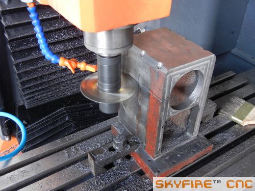
I finished the last head conversion works for the 80mm high speed spindle today. My solution is as following, similar to many high speed spindle mounts.
Firstly I drilled the 6 screw holes and milled the screw plates.
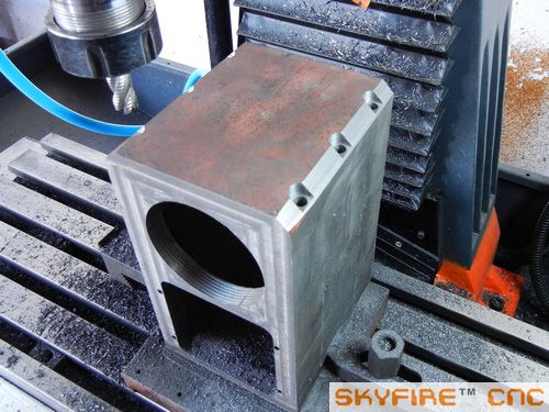
And then split the head to half with a saw blade cutter. This's really a hard part because the HSS cutter weared very quickly.
Finally...
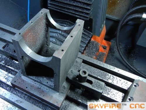
Placed a 80mm high speed spindle on
Close the head cover..The spindle circle just fit in very well. And only need 6pcs long screrws now to fasten the spindle tight.
I have considered just cut one side of the head and clamp the spindle with screws on one side. But it will need a very long screw tap and long drill tools. So I decided to cut both sides so can screw the holes easily. So.. The head conversion for 80mm spindle is completed.www.skyfirecnc.com
Email: [email protected]; Skype: skyfirecnc
-
10-02-2013, 04:37 PM #412
Registered
- Join Date
- Jul 2011
- Posts
- 441
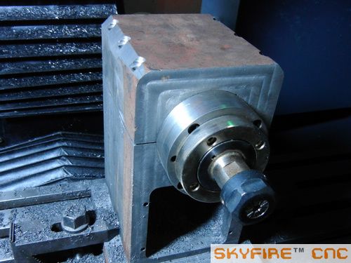
Hi handle, I just saw your comments about the 4th axis. Yes.. I have a 4th converted from manual rotary table. quite a nice one.. I think should be enough for SVM-0. Here is the 100mm(4") one I plan to use: tail stock is avaliable too.
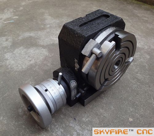 www.skyfirecnc.com
Email: [email protected]; Skype: skyfirecnc
-
10-02-2013, 07:05 PM #413
Member
- Join Date
- Sep 2006
- Posts
- 6463
Hi Sky....you must be psychic.....LOL........I was just doodling on my graphics pad about a solution to mounting the fast spindle to the head and I thought why not bore the head for the diam required and cut it off at the centre, then add two straps across the opening to clamp the spindle in, similar to the fitting on the 3020 3040 and 6040 CNC router spindle mounts on the Z axis......I did not imagine the 6 screw holes through the other part of the head........much neater than two straps, and you practically can't see the join.
I agree completely that only one half of the head sawn through with long bolts would not work really well.....the casting is being sprung to clamp the spindle.......better to have it completely sawn through on both sides.
BTW........pedantic me is being a pain in the b...m again.....the 4th axis with the rotary table conversion is not a good idea .......in my opinion.....too many moving parts and the bronze worm wheel will wear as it's under more loads than just indexing and clamping.
Backlash being the main problem in worm dives, and in the rotary table types the eccentric worm adjustment only takes out wear on a continuing basis as the wormwheel deteriorates.
The type of design I have in mind is a simple block of aluminium bored through to have two deep groove radial bearings to carry the spindle with mounting for an 80mm 3 jaw chuck, although I think if there were to be 4 sealed deep grooved radial bearings stacked in the housing and retained with a circlip in the bore at the back end and a cover plane at the front end, the life would be a hundred years or more.....never wear out.
As the load from the cutter is mainly radial to the spindle centre line, there is no real need to go to angular contact bearings to resist axial thrust and complicate the design.
I think that a 1:10 toothed belt reduction on the back end will suffice for simplicity and supply the resolution anticipated in the useage, but I have in mind a design using two sets of gears, compounded and closely meshed to give almost zero backlash.....mainly because I think a toothed belt will have some spring from the effects of the cutter forces, whereas a gear drive is totally solid.
I see there are a number of 4th axis drives on EBAY using the toothed belt system, and some with a direct stepper to the spindle......resolution being lower in the latter case.
I realise that the rotary table does offer an almost instant 4th axis with the addition of a stepper and a huge increase in the resolution by virtue of the 1:60 reduction, but I'm not all that wowed by bronze worm drives for backlash free longevity.
The toothed belt drive would be my second fall back solution, but the geared drive would be my preference.......just gotta make it.
Thanks for the order info.......the cards are now on the table......there's 85 days to Christmas, so with fingers crossed I may get a big Christmas stocking this year.....LOL.
Ian.
-
10-03-2013, 02:54 PM #414
Registered
- Join Date
- Jul 2011
- Posts
- 441
Hi handle, that's really amazing! You have exactly the same idea together..hahaha..I think maybe this is the best solution here somehow.. so we get the same conclution..:cheers:
About the 4th solution.. I'm not very sure abou the worm system inside especially the machining accuracy and quality of fit. These two are very important for such type rotary tables about accuracy life. I know many such rotary tables now and may wear out soon. I will look into it to check soon. But the worm type rotary is the best rigid solution and be able to provide high solution with 1:90 ratio and X motor solution again. The industrial ones are all use this type transmission.. but of course, much higher accuracy worm system " vairable lead worm system". that type is high accuracy and almost zero backlash..but, very expensive.
I know many easy solutions as you said with belt drive or direct drive by a motor. The degree solution will mostly depend on the motor itself. Should be enough for engraving common soft materials. I have had similiar solution with reduction stepper motor. be better than belt drive but accuracy reduction part is expensive too.. I will see, maybe can start with a belt drive one or reduction motor one, depend on its backlash. But an advantage of the worm type is that, it can be used horizental, or vertical both.
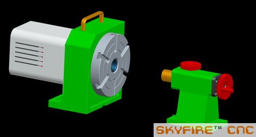
My design image:
Sure.. Anytime you can contact me directly...Christmas is comming.. I'm sure there will be some extra gift to your stocking..
www.skyfirecnc.com
Email: [email protected]; Skype: skyfirecnc
-
10-03-2013, 03:08 PM #415
Registered
- Join Date
- Jul 2011
- Posts
- 441
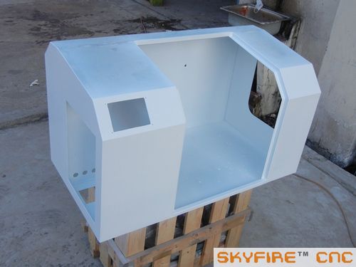
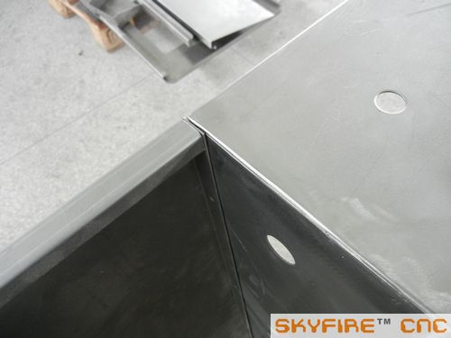
Today's progress:
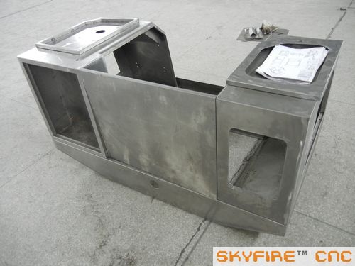
I painted half of the full enclosure.. I couldn't paint all surfaces because it's structure is some complex. I will finish other sides after several days. This was not a easy part to do because some places the sprayer was hard to reach. So need to grind some tear drops and do finishing coating again. Totally...seems not bad
I will put this part work totally to my sheet metal supplier after confirming every size on this first one...
 www.skyfirecnc.com
Email: [email protected]; Skype: skyfirecnc
-
10-05-2013, 07:57 PM #416
Member
- Join Date
- Sep 2006
- Posts
- 6463
Hi Sky, nice bit of metal working on the enclosure....trying to DIY something of that quality would be extremely hard......not many of us have the sheet metal machinery to achieve the accuracy of the cuts and bends etc.
Ian.
-
10-06-2013, 08:06 PM #417
Registered
- Join Date
- Jul 2011
- Posts
- 441
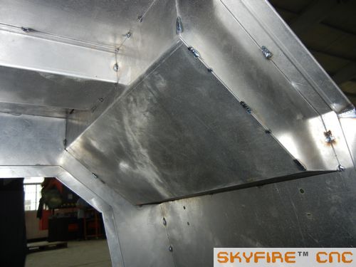
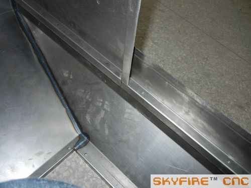
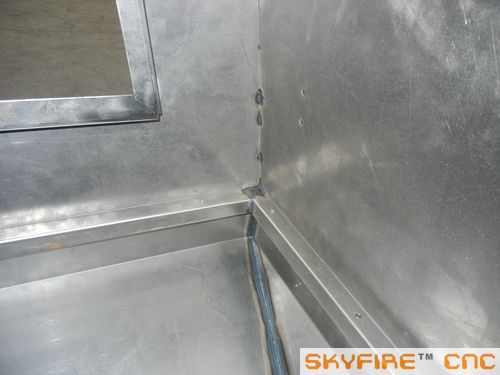
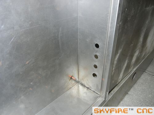
Hi handle.. It seems that we have not talked about metal sheet works in this thread. This small enclosure really cost me very much time to make it good quality because It's the first one and I need to decide many details during the process. I drilled more holes than original design to have upgrade possible with extra electrics like VFD connectors, worklight, 4th axis connectors and unknown usage..Hehe. So customer will not need to drill holes to destroy paint in future. Originally Posted by handlewanker
And the painting works is really a hard part because it's complex structure and spray gun is hard to reach the corners. So I think I at least need to paint it 4 times to finish the work.. We do have a powder coating device in my facility.. but the in--out door is too narrow for the whole enclosure. But the small easy electric box for standard SVM-0 and SVM-1/2 will be no problem to use it. I will take some pictures of the Powder coating line later.. but really a dirty workroom there..
So... Let's get back to metal sheet subject.. I will organize the formal sketch of the enclosure and will ask my metal sheet side to build the enclosures next..So I think I won't need to do this job again.. I have some pictures of a bigger enclosure under building for one of the SVM-2 version. Pretty good process there with the CNC punch and professional workers. So I'm sure the metal sheet quality will be quite reliable.
 www.skyfirecnc.com
Email: [email protected]; Skype: skyfirecnc
-
10-06-2013, 08:17 PM #418
Registered
- Join Date
- Jul 2011
- Posts
- 441
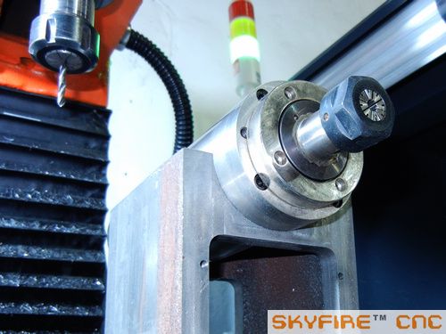
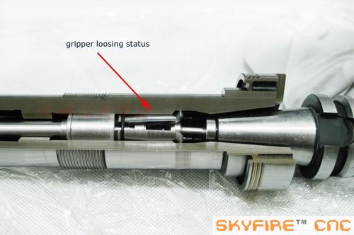
And,, Seems some guys really have interests on my BT30 spindle unit.. So I take some more pictures yesterday and post here for reivew now. This spindle we have present many pcs in store and will sell seperately under SKYFIRE brand..Have several types for selection with different bearing configration and MAX speed. So you guys can contact me if need a low cost, high quality BT30~
")
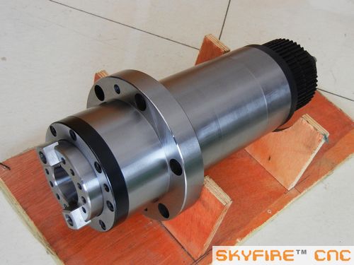
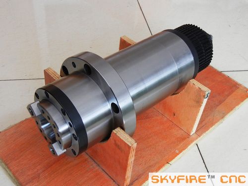
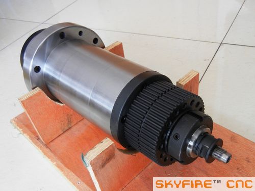
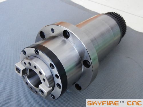
We even have a axes split to show the gripper and drawbar details inside.
 www.skyfirecnc.com
Email: [email protected]; Skype: skyfirecnc
-
10-06-2013, 08:25 PM #419
Registered
- Join Date
- Mar 2013
- Posts
- 124
Considering that some folks buy Tormach heads for projects (like another seen in this section), it would be interesting if you were to offer head assemblies (casing, spindle, and/or motor)
-
10-07-2013, 05:14 AM #420
Member
- Join Date
- Sep 2006
- Posts
- 6463
Hi Sky, that BT30 spindle looks very professional.......I'm awed by the design of the gripper inside, it looks so logical when you see it in the light of day.
One thing I wanted to ask about...........now that you have achieved the splitting and clamping of the the head casting for the 80mm spindle special order, and seeing as how I am impressed by the nature of the clamping arrangement, can we order the SVM-0 with a split head too, to hold the ISO20 and 65mm high speed spindles.......this is so much better than a ring of bolts on the bottom face........in my opinion, very humbly.
BTW, it was indeed very fortuitous that the side wall thickness of the head allowed you to have the opportunity to drill and tap into it for the retainer bolts.....normally one would expect the wall thickness to be quite thin to save on weight in the Z area.
The last question is..........with the ISO20 spindle does the draw bar end have the retainer pin gripper arrangement for tool retention like the BT30 spindle, or is it just a screwed end into the end of the ISO tool shank?
I can't remember if it was so when the ISO 20 spindle was mentioned as the solution to tool changing back in the posts previously.
Without the retainer pin/gripper arrangement on the end of the drawbar (for QCT) like the BT30, there would be no point in having ISO 20 tooling as the screw in drawbar makes it only manual and very time consuming to release the tooling, which is what I wanted to avoid with the ER set-up.
I hope this can work out as I'm on the starting blocks waiting for the starting gun....LOL.
Ian.

Similar Threads
-
Show us your machine stands
By OHLEMANNR in forum Benchtop MachinesReplies: 7Last Post: 05-05-2013, 03:19 AM -
a machine design (pics) from beginning to end
By blurrycustoms in forum Vertical Mill, Lathe Project LogReplies: 42Last Post: 04-25-2013, 02:36 AM -
dry build or glue from the beginning?
By Ezra in forum Joes CNC Model 2006Replies: 2Last Post: 10-29-2010, 04:44 AM -
Newcastle: Beginning of build plan
By pippin88 in forum Australia, New Zealand Club HouseReplies: 7Last Post: 09-16-2010, 10:22 AM -
Beginning to build my Z-axis.
By zonk2 in forum DIY CNC Router Table MachinesReplies: 0Last Post: 12-23-2008, 06:17 AM
