


Im going to attempt a build log as per request.
Background. A few years ago I was interested in watercooling computers. Not wanting to buy already made stuff, I wanted to design them and make them. So I got interested in CNC. I purchased the MAXNC 15 OL machine with the shallow promises from the company that the machine is stout enought to machine copper. Well guess what... it will machine copper. If you take shallow cuts and run a VERY SLOW feed. not what they told me. Anyways. So I was bound and determined. I setout learning the machine and cad. A friend of mine that works at a machine shop was a valuable resource to me. And still is. While learning the machine the driver control box took a dump. Maxnc wanted $375 for a new one. and it was under 6 months old. So we found a guy that did a board level repair. it works again. I kept throwing belts. It was a problem. Finally we traced the prroblem to the cheesy flimsy motor mount system. We machined a newer more rigid mount. Belt problem solved. Well a few months of 9 IPM rapids later I was getting used to this machine, then the control box takes a dump again. And the spindle speed control know. To fix the spindle speed i got a router speed control know and wired it up. Also put a light switch in the box with the speed controller so I could instantly kill the power to the spindle in case of E stops. Works great. So now that takes us to the dead driver. Called up MAXNC again. $50 an hour to diagnose and a 6 month lead time, or again the same $375 to replace the box. BS. I will no longer deal with them at all! NEVER, NA DA! Did some researching and came across the ZYLOTEX company and product. price was perfect so I ordered the 4 axis driver, 24V power supply and cooling fan. Still way under the $375 replacment cost from CRAPNC. Got it all wired up, asked questions, drove Jeff bonkers with emails im sure. but alas It was up and working again. The OEM powermax II 114OZ steppers I thought were under powered. But I did get a 15 IPM max rapids with just the Xylotex driver. After much talk with Jeff from Xylotex he told me that with his kit and his 269 OZ steppers that people were getting 40 or better IPM on their Taig and sherline products. I was hooked, I ordered 3 of the 269 steppers and Mach 3 while I was at it. That is when the big trouble started. After installing the 269`s I could not get past 18 IPM due to resonce in the steppers. missed steps, sounded horrable everything. now its back to driving Jeff mad again with emails. i will say this, EVERY SINGLE EMAIL I SENT WAS ANSWERED. he seemed to think some of the problem was due to the solid couplers that the maxnc came fitted with. So I set out to design and make some flex couplers. and well that is where I am now... ill post some pics now......... More to come.
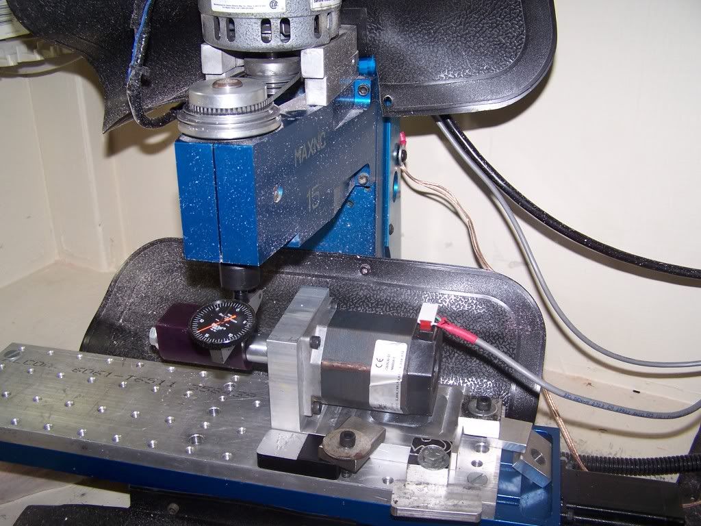
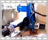
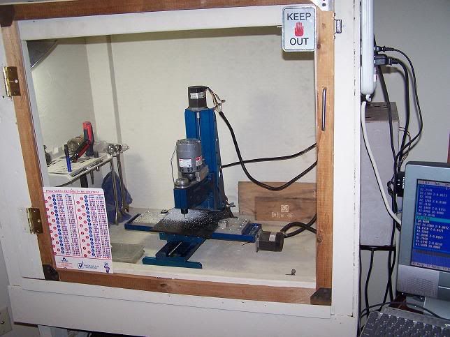
The machine with just the Xylotex driver installed. Stock motors
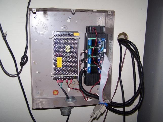
The Xylotex driver board setup in an old Curcuit breaker box
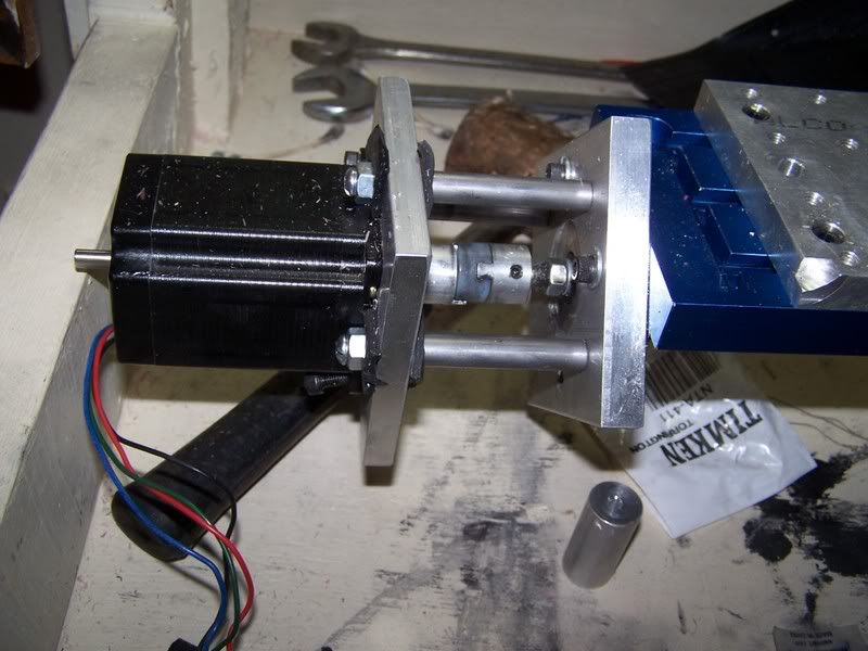
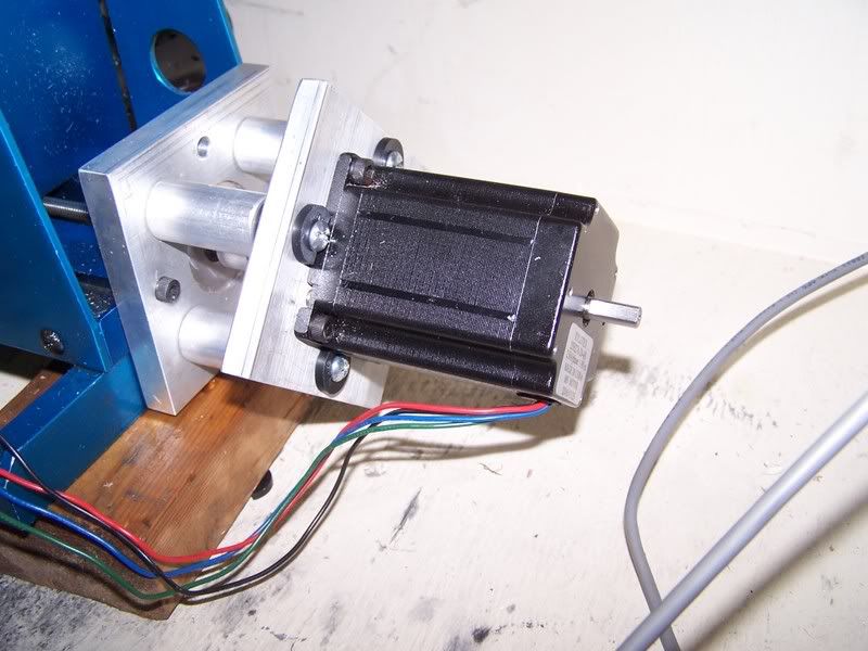
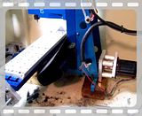
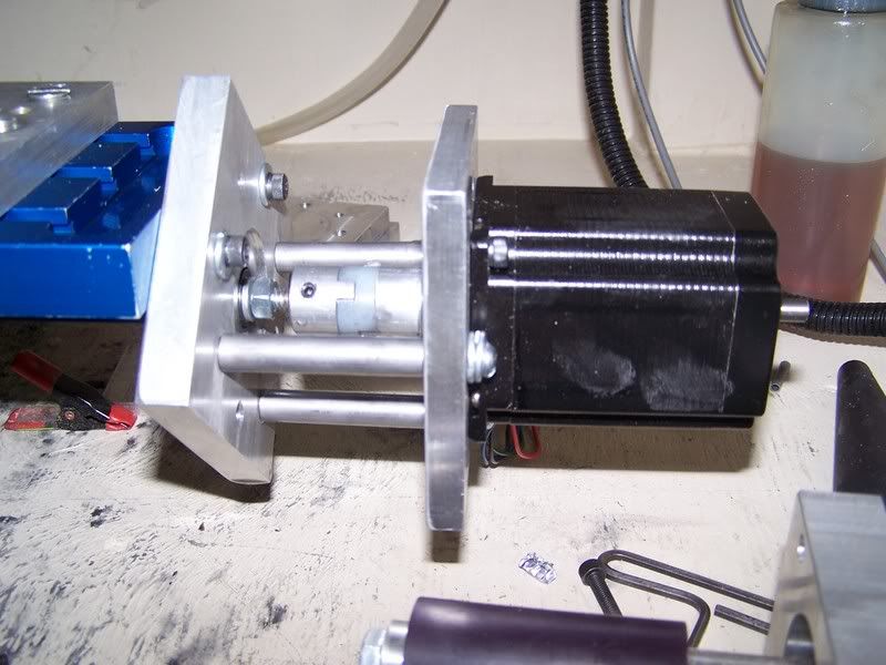
Here are the flex couplers that we made.
Installing on the X axis
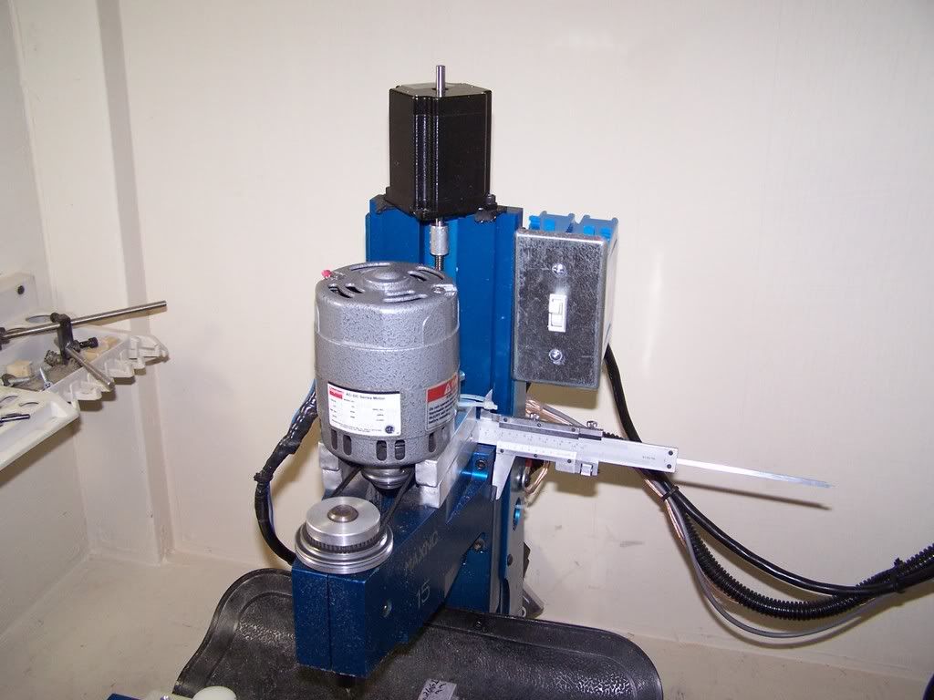
This pic shows my home made 4th axis for machine wax. Also not the beefy dove tailed Spindle motor mount.
Results 1 to 20 of 48
-
01-23-2007, 12:54 AM #1
 Registered

- Join Date
- Jul 2006
- Posts
- 887
My MAXNC 15 OL mill and conversion.
-
01-23-2007, 01:12 AM #2
Registered
- Join Date
- Jul 2006
- Posts
- 887
So, the last couple of days I have been engaged in a few threads on this forum. Seems that after I did all this, I was still locked at 20 IPM due to resonce (Dont mind my spelling) Around 18 IPM My motors would sound like crap and loose steps. To counter this, I found that if i lowered my Vref settings on the driver it would allow me to tune away the problem. not really a suitable fix but with me mainly machining wax and MDF it was a solution to get my machine back working. And i lived with it for months. Anyways, reading some of the current threads here, I found that others were getting the same type of problems. And I cought the tweak but again. So i started tinkering again. Re-read the paperwork that came with my PSU and found that it could be adjusted to 27V and still work with the XYLOTEX. So I did. No change.
Upped my Vref voltages back to 3 v on the X axis. The growling problem returned. And stalled all over the place.
See short vid of problem
After reading some posts I thought it might be a mis-alignment problem So I started tweaking that. Re-align and tighten down mounts. No change. Then I read that someone had their motor screws lossened up and his machine sounded good. So I tried it. Sure enoughtwith all 4 screws loosened up on my bigger mounting plate it was fast and quiet. I stated shimming things. maybe Im not aligned right. Nope! that wasnt it. So I started playing with running the axis back and forth and adjusting the tightness on the bolts. I could tighten one bolt down and it was smooth, quiet and fast. But if I tightened another one even a turn or two it all went to hell. Scratched my head.
Read somemore of the threads I was involved in and someone was using rubber groumets between the motor and the machine. Sounded good..... but it was late in the evening and I was fresh out of rubber gromets. I went into my back building and scavanged around. All I could find was some 1/2 in fuel line. But it was rubber. So I cut some up and drilled holes in it. Mounted the motor to the machine and started up the X axis. Slowly I tightened the bolts. MUSIC!!!!!!! It was fast, quiet and pretty tight as to not having to worry about something falling off.......
Here is the video of it running.... notice my rubber insolators.

-
01-23-2007, 01:22 AM #3
Registered
- Join Date
- Jul 2006
- Posts
- 887
With this new found speed I was excited again about finishing my thrust bearing conversion. I went out today and got some thrust bearings, washers and a few other odds and ends. I looked for some rubber mat to use instead of my crude fuel line setup. I couldnt find any, but what I did find was some 3/8M Flat faucet washers with a 21/32 OD. In the plumbing dept of the hardware store. a 10 pack of these washers were on sale for $.59 so I grabbed a few. Headed home with my suplies eager to get it all working!
Alas i tear down the Y axis to installe the adaper plates and flex couplers and thrust bearings. Disaster strikes!
I pulled out the all thread and dug out the new all thread I purchased a few months back. I needed longer rods to accomidate the new hardware. Got to looking at these two rods side by side. OHH CRAP!!!!! one is 1/4-20 all thread (The new one) and the old one is 1/4-20 ACME thread. ok, no biggy, I still got the longer ACME rod that came OUT of my X axis when I did the conversion. I threaded it into the BSA nut on the Y axis and went to install one of the 1/4-20 regular nuts i was going to need for the inside thrust bearing. It wouldnt thread on the rod. But wait a minute, these are the same zink nuts I used when I did my X axis conversion. "OHHHH SH!T..."
I put a standard 1/4-20 all thread on my X axis and have been running it that way for a few months!!!!!
Called and found some 14-20 ACME all thead. I just hope I didnt chew up the inside of my BSA nut!
DAMNITT!!!!!!!!
-
01-23-2007, 02:22 AM #4
Registered
- Join Date
- Jul 2006
- Posts
- 887
Ok, did some thinking and searching. I need to get my regualr ol ZINK 1/4-20 nuts to thread onto the ACME rod. For securing thrust bearings ect. So I called Paul, My machinist friend and asked him. "Could I re-tap these zinc nuts to ACME threads?" he said sure! So I went looking for a 1/4-20 ACME tap. Apperantly its a hard to find item. The only way I found to get one was to have it custom made. Im still steaming about not noticing this thread difference back when I did the X axis. Its been running this whole time with a standard all thread rod. ARRGGGH.....
Ok, my girfriend says that if it was easy it wouldnt be fun........ so, Does it have to be this much fun?????
So, re-tapping the nuts is out. So i called paul again......"Hey, can I re-thread this acme rod to 1/4-20 standard? i only need to re-thread about an inch and a half on the end. This way i can get my standard nuts and such to work. So that is the plan for tomarrow. Swing by the machine shop, steal a Die and maybe some aluminum. Whats the aluminum for? Nothing really, its just good to have material on hand for small projects. While Im there, I might as well swipe some WAY LUBE as well. Im running low.
-
01-23-2007, 08:30 AM #5
Registered
- Join Date
- Mar 2004
- Posts
- 44
I had similar resonance issues. I made harmonic dampeners from 2.125" diameter aluminum hubs. I bored the center out and put a rubber hub in. I put these on the shaft at the opposite side of the motor. I can easily spin these to over 70ipm without resonance. I have a Taig, so I only run it up to 30ipm during use....I don't think the stock lead screws are meant to be run constantly above 30ish. Before this mod, I would occasionally miss steps during rapids. I had originally needed to set Vref at about 2.5 as at 3.42 it would instantly stall. With the dampeners, I run at the full 3.42 Vref recommended.
Good luck,
Jim
-
01-23-2007, 02:49 PM #6
Registered
- Join Date
- Jul 2006
- Posts
- 887
jim, do yo have any pictures of these dampeners?
-
01-23-2007, 03:06 PM #7
Registered
- Join Date
- Jul 2006
- Posts
- 887
James over at another thread Im watching had a really good idea. The dynamat could be a good way to kill vibrations. here is a cut and past of his idea
hope this helps. I was thinking that one could make a damper out of some Dynamat. It is used to dampen road noise and vibrations in automobiles. The displays at Audio stores have a 1/4" square piece cut out of a sheet that is stuck to a "assistance bell" (like the ones on hotel counters) and all it does is go thud, no ring. It absorbes the vibration! Something else that I just thouight of is one could turn down some foam rubber hockey pucks, drill a hole in the center and put some washerws on either side. ????? Good luck!!!! James
Here is the thread.
http://www.cnczone.com/forums/showth...t=30095&page=9
-
01-24-2007, 09:01 AM #8
Registered
- Join Date
- Mar 2004
- Posts
- 44
I'll post a few pictures when I get a chance.
Take care,
Jim
-
01-24-2007, 11:40 AM #9
Registered
- Join Date
- Mar 2005
- Posts
- 266
Have you considered using servos?
-
01-24-2007, 05:10 PM #10
Registered
- Join Date
- Jul 2006
- Posts
- 887
servos is out of my price range..
Well I looked and the cheapest I could find ACME 1/4-20 screws totals $30 for 3 2 ft peices. Plus shipping. Anyone know a cheaper plase to get them?
I also found that is a total pain to use a regualr 1/4-20 die to re thread the end of an ACME all thread rod.
-
01-25-2007, 01:37 AM #11
Registered
- Join Date
- Jul 2006
- Posts
- 887
More work today on my flew coupler conversion. having sorced some lead screws i was not happy with sitting idle. I just dont sit still very well.
I took my original X axis lead screw and measured it. Its about an inch longer then the screw in my Y axis, so I said to myself, I said "Self, why dont I use the X axis screw that I took out for the Y axis" and it was on. I am having to use standard 1/4-20 hardware for my setup. Nuts to hold thrust bearings and such. I thought why not get a 1/4-20 ACME tap and just re tap my zinc nuts. Peice of cake. Untill I started searching for a damn TAP. I found one place that would make me one for the tune of a littl over $200. SCREW THAT!!!! Im cheap. So I called Paul, my machinist friend. Asked a couple of stupid questions... then formed a plan. I would head up to the machine shop and steal me a standard 1/4-20 DIE. So I did. Got how and rethreaded the ACME screw end about an inch deep. It wasnt easy but I finally won. This allows me to thread on my standard nuts and everything. HAPPY TRAILS!
Until it happens. My girlfriend talls me "If it was easy, it wouldnt be fun" Does it have to be this much fun?
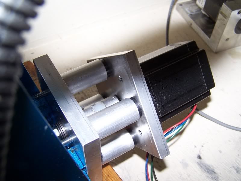
Here is the deal. The lead screw is just long enought to hang past my thrust bearing mounting plates I made. I cut some 2 inch spacers, then another plate that the stepper bolts to. Flex coupler goes inbetween and makes the connection. Well my stand offs were to long. Once everything was fitted the couplers didnt touch. In fact they were about 1/4 in away from each other. So my brain starts working and I came up with an easy solution. Shorter standoffs. Drats, no lathe in my building yet. So off to the machine shop I go. I cute me some 1.5 in stand offs. Alot thicker then my tubing ones. Should hold better.
Put everything together and OHHH ITS PURDY, QUIET, and FASTER! I also used faucet wahsers to insolate the stepper motor plate. no more nasty resonence.
And now for the PICS......
X axis setup. notice the lengeth of the standoffs.
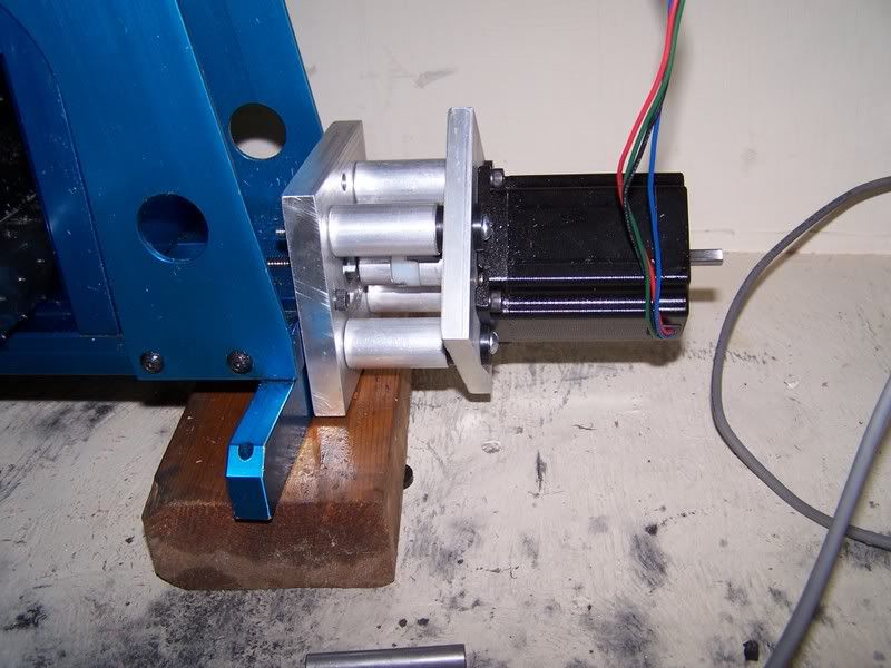
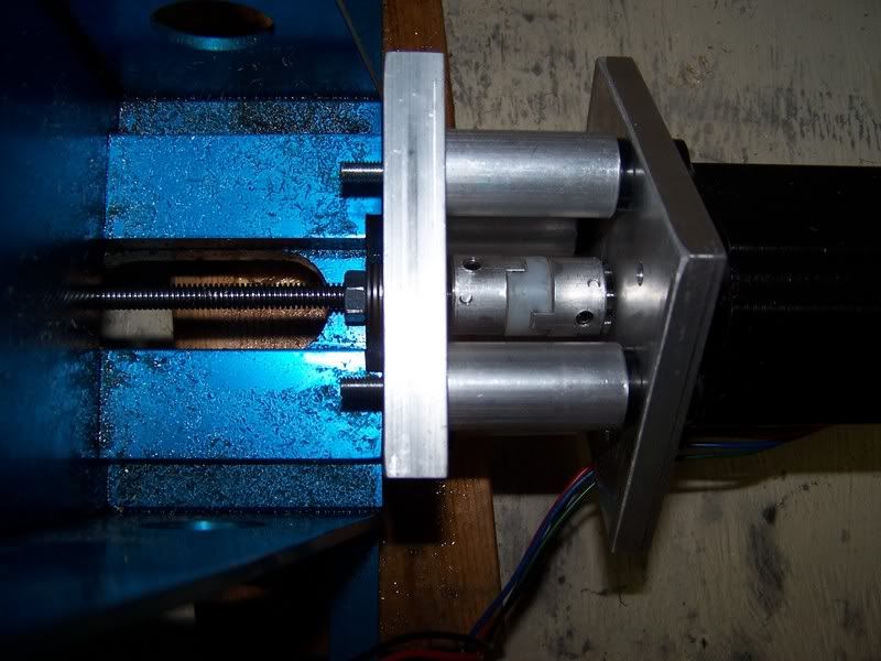
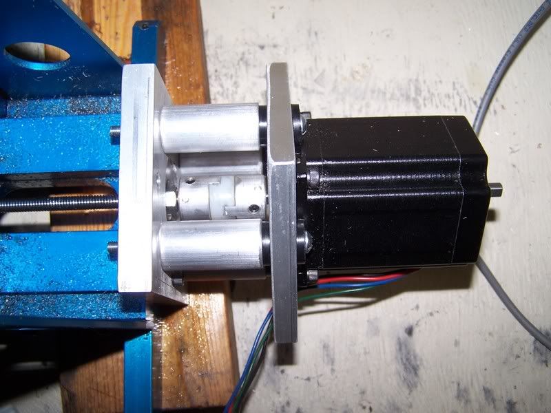
Y axis mods. Shorter standoffs help in the clearance issues in my machine inclosure as well. I have the machine turned sideways in the box to get to the hardware.
Thrust bearings
-
01-25-2007, 02:24 AM #12
Registered
- Join Date
- Jul 2006
- Posts
- 887
Just took this video of my Y axis running. 40 IPM and music to my ears.
-
01-25-2007, 02:40 AM #13
Registered
- Join Date
- Jul 2006
- Posts
- 887
Another video of it running 46.88 IPM the highest setting mach 3 will allow me with 32000 steps per inch.
-
01-25-2007, 03:38 AM #14
Registered
- Join Date
- Mar 2005
- Posts
- 266
Still having resonance issues at lower speeds?
-
01-25-2007, 05:43 AM #15
Registered
- Join Date
- Jun 2006
- Posts
- 823
Sounds very good! Originally Posted by Fixittt

-
01-25-2007, 06:25 AM #16
Registered
- Join Date
- Jul 2006
- Posts
- 887
18 ipm and the motors are just a little louder, so Im guessing just a bit of res. there. Nothing like it was before and it hasnt lost any steps. Originally Posted by Smertrios
God i wish I had my other ACME lead screws i would redo the X axis and then do the Z. Then on to making parts!
[I] think that I am going to do away with the 2 inch tubes I have on the X axis and just make some new nicer stand offs like I made for the Y axis kit. they just look butter and more sturdy. Even though none of the cutting forse is applied to them. it just looks better.
-
02-17-2007, 12:14 AM #17
Registered
- Join Date
- Jul 2006
- Posts
- 887
Nope. all issues seem to be gone.
-
02-17-2007, 12:25 AM #18
Registered
- Join Date
- Jul 2006
- Posts
- 887
Ok, so I finally found a source for my lead screws. They have been ordered. I have still been using the machine to cut wax jewlery models. I run alot of long codes, sometimes taking 6 to 8 hours to complete. Having to babysit the machine is not all that fun. My spindel motor isnot automatic on and off like the higher end machines so I devised a way or having it shut off at the end of a code.
-
03-13-2007, 11:13 PM #19
Registered
- Join Date
- Jul 2006
- Posts
- 887
So, its been over a month now and I finally for my 1/4 20 acmes lead screws in......FINALLY!
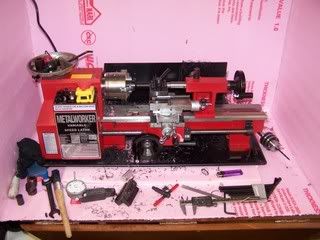
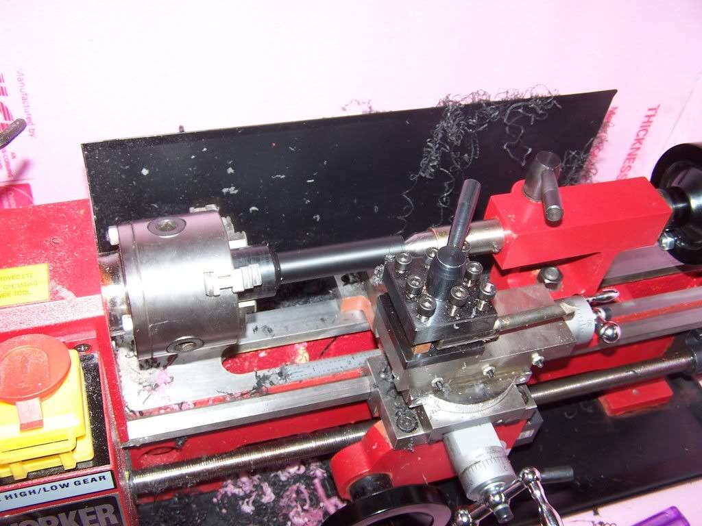
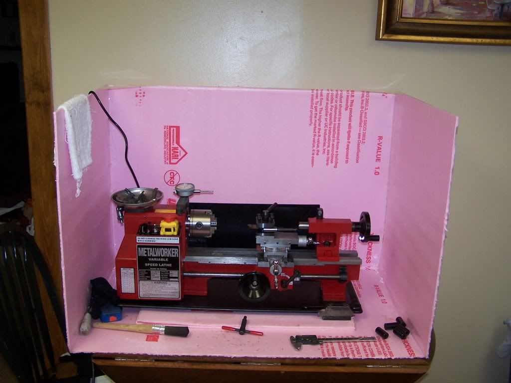
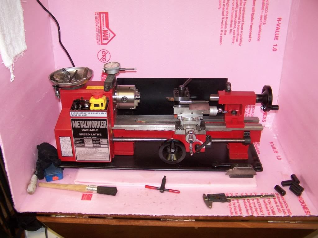
I also picked me up a wholesale tool mini lathe. It pays to know people, Not only did I get a 10% discount, but I didnt have to pay tax..... a $50 + savings!
So I got my lead screws in for my X axis and my X axis...... I descided that I didnt want to make my adapter plate stand offs out of alminum, so I used to black delrin. Used the mini lathe to drill, turn down and cut to length the stand offs. Im liking that 8X10 lath more and more. One of the resons I didnt want to use aluminum was because my girlfriend let me put the lathe on the kitchen table and I didnt want to shred aluminum and have it get everywhere.
Here are some pics of it in action. Ohh those are the stand offs at the bottom right corner of my makeshift box.
-
11-24-2007, 08:12 AM #20
Registered
- Join Date
- Jul 2006
- Posts
- 887
A bit of an update. I thought that the resonance issues were solved by the home made love joy connectors and thrust bearings, but the stupid issue reared its ugly head again. So I found the thread on the "Rattler dampeners" and decided to make me a set. These things ROCK! Easy to make and have been very reliable. Now the plans called for .5 in rods to be set into .20 over sized pockets in the dampener. Well, I had some .5 in ball bearings on hand and guess what. they work like a charm. I have been running this was for some time and it has shown to be very reliable. My only complaint is that I made the bottom half out of delrin and the set screws tended to loosen up and I would loose steps. Longer bolt and some silicon RTV seems to have solved that problem!
Here are some pics.


 Reply With Quote
Similar Threads
-
My mill Conversion
By phatfred8 in forum South Bend MachineryReplies: 50Last Post: 10-10-2018, 02:37 AM -
MAXNC UK conversion
By keith101R in forum Benchtop MachinesReplies: 0Last Post: 08-06-2006, 05:41 PM -
CNC mill conversion
By alnicov in forum Knee Vertical MillsReplies: 4Last Post: 07-07-2004, 10:47 AM -
MaxNC motion kit for Sieg X3 mill?
By replicapro in forum CNC Machine Related ElectronicsReplies: 3Last Post: 06-16-2004, 06:24 AM -
Maxnc Mill
By Dort in forum Uncategorised MetalWorking MachinesReplies: 1Last Post: 02-07-2004, 04:56 PM
