


I need help with changing from 440 to 220.
I have one wiring diagram, Its in German though. I scanned it and have inserted it.
There are 2 motors that need to be changed over. The first motor is the first picture and the scanned wiring diagram.
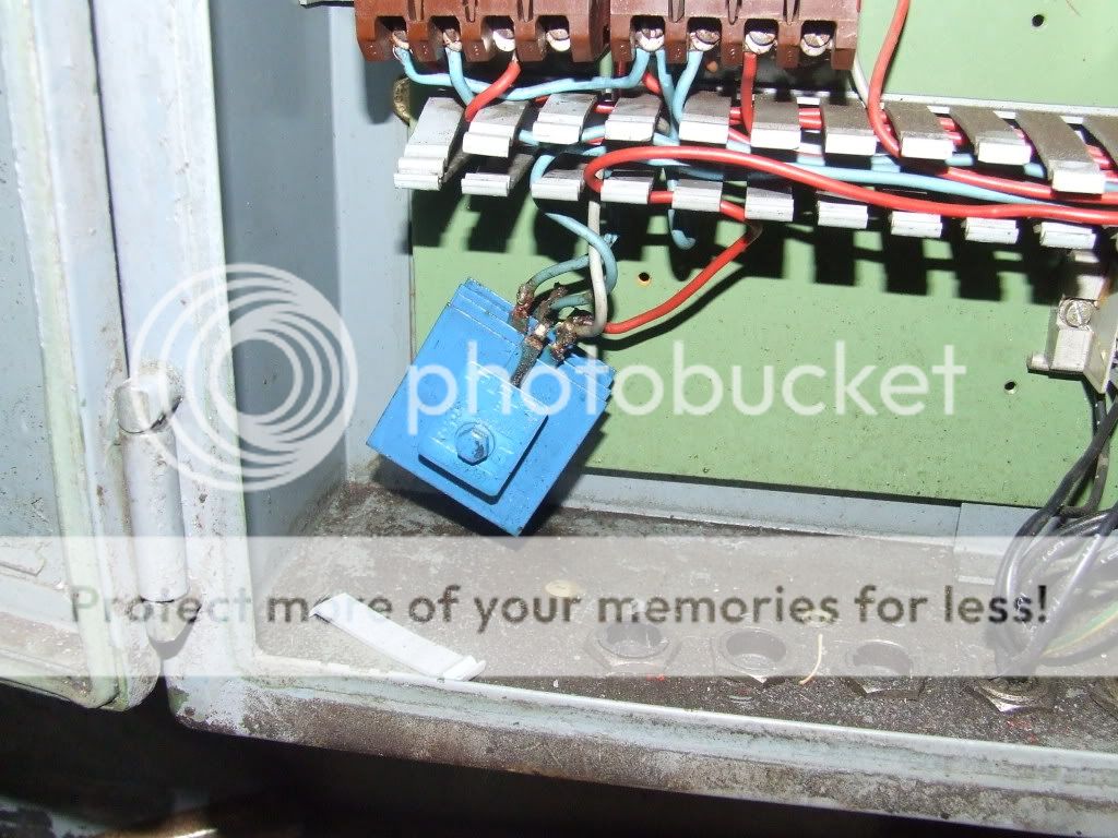
The 2nd picture is the 2nd motor.
Any help is appreciated.
Here is the scanned diagram for the wires in the first picture.
Hohe Spannung is "High" and the other one Niedrige Spannung is "Low"
And here are the wires for the 2nd motor without a diagram.

Results 1 to 20 of 29
-
11-28-2009, 07:36 PM #1
 Registered
- Join Date
- Nov 2004
- Posts
- 239
Pehaka horizontal saw wiring diagram
-
11-28-2009, 10:38 PM #2
Community Moderator
- Join Date
- Dec 2003
- Posts
- 24223
The first motor is fairly straight forward, the jumpers just need to be changed, the second appears to have 6 wires coming in, the reason may be is it possible that this motor may have been started with a star-delta starter or a two speed controller?
Is the wiring still present for the second motor, if so it may need a bit further investigation as to what feeds it.
Al.CNC, Mechatronics Integration and Custom Machine Design
“Logic will get you from A to B. Imagination will take you everywhere.”
Albert E.
-
11-29-2009, 03:04 AM #3
Registered
- Join Date
- Nov 2004
- Posts
- 239
The jumpers as in the little metal plates? or would the 3 wires move to the 3 points opposite where they are connected now?
-
11-29-2009, 05:20 AM #4
Community Moderator
- Join Date
- Dec 2003
- Posts
- 24223
If the top motor is connected for 440 now, then the jumper plates would be moved up in the picture and the bottom three would be jumpered across horizontally.
The three phase in would go to each of the three jumper plates.
IOW, the terminal box is upside down to the picture.
Al.CNC, Mechatronics Integration and Custom Machine Design
“Logic will get you from A to B. Imagination will take you everywhere.”
Albert E.
-
02-19-2010, 07:00 PM #5
Registered
- Join Date
- Nov 2004
- Posts
- 239
Got another issue
I have one more small issue before I can move on with this project.
I got a new hydraulic solenoid valve.
Electric stuff is not my strong point obviously. I need some help in wiring up the solenoid valve.
The saw operates like this:
Press one button to turn on the hydraulic pump. The pump will stay on until I hit a seperate button to turn it off.
There are two different buttons for the two different solenoids.
I have no idea what combination of buttons will work to raise and lower the saw. I'm not sure if I would need to hold the button to keep the solenoid energized or if I would need to press another button to disengage the solenoid.
There are 3 wires coming from the saw. Green/yellow, Blue, Brown. I've figured out the grn/yellow is ground.


-
02-19-2010, 07:45 PM #6
Community Moderator
- Join Date
- Dec 2003
- Posts
- 24223
First you would need to know whether you have to retain power to the solenoids while in position, or if on only until up or down is required.
This decides the logic required, the most simplest is if sol. power is only need to raise and lower with no retention.
You could do this just by applying power to one or the other in turn and see the results.
Wht-Blk or Red-Orange.
Al.CNC, Mechatronics Integration and Custom Machine Design
“Logic will get you from A to B. Imagination will take you everywhere.”
Albert E.
-
02-19-2010, 08:50 PM #7
Registered
- Join Date
- Nov 2004
- Posts
- 239
I applied 21V+ to White and grounded the other wire. The directional light came on and stayed on. I did the same with the other wire combination and the other directional light came on.
The same button that turns off the hydraulic pump turns off the solenoid. There is also a round switch that turns and can be in an "in" state or an "out" state.
I used my multimeter and hooked the black probe to the grn/yellow wire. I hooked the red wire from my meter to the blue wire coming from the saw. When I pressed one button on the control panel the meter read 26V+ When I pressed the other button the 26V+ went to less than 0V and fluctuated. I tried the same procedure with the brown wire coming from the saw. No button combination got any + volts from the brown wire.
Saw Start and Saw Stop should be Blade Start and Blade Stop instead.

-
02-20-2010, 06:14 AM #8
Registered
- Join Date
- Nov 2004
- Posts
- 239
I did some wire tracing and came up with some more info.
The 3 wires come from the solenoid and connect to a relay. There are 2 relays jumpered together. I'll upload some pictures tomorrow. Only one relay engages and disengages when I push the buttons. There is something that looks like a diode that is wired into the relays.
Another thing that struck me as odd was that the green/yellow wire doesn't go to ground. It goes to the relay. There is also a red sleeve over the green/yellow wire.
-
02-20-2010, 09:55 PM #9
Community Moderator
- Join Date
- Dec 2003
- Posts
- 24223
This is why I mentioned to get the required logic, as it sounds like you might have the solenoids kept energized by each relay and they are interlocked so only one can be energized at the same time.
It would be best to carefully reverse-engineer it and draw a schematic up based on the results, then it can be connected properly.
I did not see any previous mention that the solenoids were 24v? Is this AC or DC?
Al.CNC, Mechatronics Integration and Custom Machine Design
“Logic will get you from A to B. Imagination will take you everywhere.”
Albert E.
-
02-21-2010, 02:12 AM #10
Registered
- Join Date
- Nov 2004
- Posts
- 239
They are 24V dc. I'll try to trace the wires and come up with a schematic
The soleniods have to be ennergized for the fluid to move.
I only have one of the original solenoids and it was the one to let the saw down. To raise the saw I would turn on the pump and push in on the pin where the missing soleniod was.
To lower the saw I would turn on the other solenoid and adjust the bleed off valve. If I turned on hydraulic pump while the solenoid was on the saw would feed downward.
I have a thread about it on another website that might help explain it.
http://www.practicalmachinist.com/vb...ic-saw-195208/
-
03-08-2010, 08:14 PM #11
Registered
- Join Date
- Nov 2004
- Posts
- 239
I'm still working on this saw. I've worked out some of the wiring and created a dxf. Can someone look at it and let me know what information is needed to get this thing working right? Do I need to trace the wires all the way to the switches?

-
03-08-2010, 10:12 PM #12
Community Moderator
- Join Date
- Dec 2003
- Posts
- 24223
I will look the DWG and get back, the first thing you want to do is get rid of those selenium rectifiers.
Al.CNC, Mechatronics Integration and Custom Machine Design
“Logic will get you from A to B. Imagination will take you everywhere.”
Albert E.
-
03-09-2010, 04:56 AM #13
Registered
- Join Date
- Nov 2004
- Posts
- 239
I've narrowed it down some. The blue wires coming off the rectifier are the common negatives for the solenoids.The brown wire and the green/yellow are for the +
I have the left solenoid working correctly but the right one is not working.
I used my meter and the two switches used for the solenoids have identical readings.
Both switches have about 12V of power on all four poles.
With no power coming to the saw the left sides of the switches have continuity when not pressed. The right sides do not. When the buttons are pressed the right sides have continuity and the left sides do not.
When I turn the power on to the saw this is what I observe.
When the left solenoid is engaged the led lights up. When the left solenoid is engaged and I press the button for the right solenoid, the left disengages but the right does not come on.
If I manually push in on the relay for the right solenoid it will come on. The relay won't stay engaged on its own though.
The #10 wire is jumped to a yellow/green wire for some reason. Looks like someone did this, certainly doesn't look like a factory thing.
I've made a pdf of the buttons wiring. I'll add more details as I get them.
-
03-09-2010, 06:39 PM #14
Registered
- Join Date
- Nov 2004
- Posts
- 239
I've made a change to the .dwg file. I jumped the #10 wire to a pole on one switch and the solenoids seem to be working properly. Can someone check it to see if I just got lucky and this is the way it is supposed to be wired up?
Also, I disconnected the grn/yellow for the upper limit switch and I would like to have that working properly. I need to know where to hook that up to have it work right.
-
03-09-2010, 09:35 PM #15
Community Moderator
- Join Date
- Dec 2003
- Posts
- 24223
It would help if you show the internal configuration of switches and limits, if four terminals are used are they N.C. or N.O. and which is which.
Also it is hard to diagnose and draw up a a control print without knowing the desired sequence of operations.
I don't know where you are getting the 12v, if these are 24v solenoids I would expect to see 24v only for the control.
What are the voltages of the relays, if marked.
Al.CNC, Mechatronics Integration and Custom Machine Design
“Logic will get you from A to B. Imagination will take you everywhere.”
Albert E.
-
03-09-2010, 11:19 PM #16
Registered
- Join Date
- Nov 2004
- Posts
- 239
The switches that control the solenoids are configured like this:
There are 4 poles. 1 pole on each corner. The poles on the left side of the switch are N.C. The poles on the right side are N.O.
The relays are not marked.
I don't know about the sequence. It seems that only one solenoid can be engaged at one time though. When selecting one solenoid it should disengage the other or lock it out from engaging.
-
03-10-2010, 12:15 AM #17
Community Moderator
- Join Date
- Dec 2003
- Posts
- 24223
That would make sense, what about the switch config of the limit switches (NO/NC?). Originally Posted by Shanghyd

Al.CNC, Mechatronics Integration and Custom Machine Design
“Logic will get you from A to B. Imagination will take you everywhere.”
Albert E.
-
03-10-2010, 01:21 AM #18
Registered
- Join Date
- Nov 2004
- Posts
- 239
It looks like the upper switch is N.C and the lower switch, one set of contacts is N.O and the other set is N.C.
The switches don't match. I wonder if one was replaced and that's why the grn/yellow wire from the upper limit switch was jumped to the #10 wire from the relay.
-
03-10-2010, 01:49 AM #19
Registered
- Join Date
- Nov 2004
- Posts
- 239
This might help too.
It seems that the green and yellow wire that is wrapped in red would go to the main power switch on the switch panel. It looks as if someone jumped the main switch with a little jumper wire.
I included a picture of the wiring diagram of the switch. The other pictures are of the solenoid switches.
-
03-10-2010, 07:07 PM #20
Community Moderator
- Join Date
- Dec 2003
- Posts
- 24223
The reverse engineering procedure can often require a lot of patience.
Rather than draw out the physical layout as you have done, it it is often clearer, in the end anyway, to draw in the form of the typical electrical logic schematic.
Two vertical lines are drawn each side of a page and the left side rail is one power conductor where the logic starts and the logic string consisting of switches push buttons etc, progresses across the page and ends up as an output on the right hand rail, output being coil, relay, contactor, solenoid etc.
a simple e.g. http://www.allaboutcircuits.com/vol_4/chpt_6/3.html
Each circuit is traced from power in to the end output device.
In this form it is easier to read and to realize the logic involved.
Al.CNC, Mechatronics Integration and Custom Machine Design
“Logic will get you from A to B. Imagination will take you everywhere.”
Albert E.


 Reply With Quote
Similar Threads
-
wiring diagram
By prabhu58 in forum Uncategorised MetalWorking MachinesReplies: 1Last Post: 04-29-2019, 08:19 AM -
320 ERR/RES wiring diagram
By schwinndk in forum Gecko DrivesReplies: 2Last Post: 10-22-2009, 11:33 AM -
help with wiring diagram for C6 CNC
By JDsto in forum Syil ProductsReplies: 6Last Post: 01-10-2008, 01:37 AM -
Wiring Diagram
By SCHMEOW in forum CNC (Mill / Lathe) Control Software (NC)Replies: 1Last Post: 10-21-2007, 05:40 AM
