


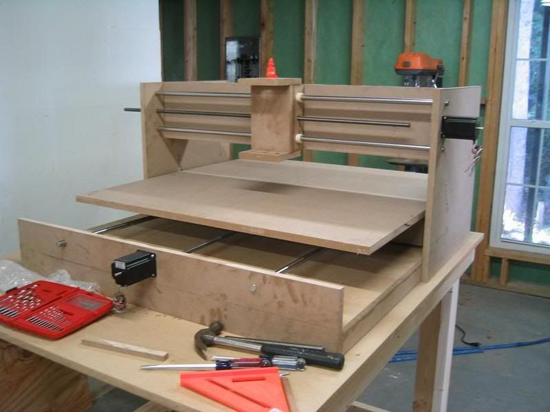
A couple months ago, a co-worker told me about his CNC machine he built at home. He answered A LOT of my questions on the general building process and I then began searching online for more designs, tips and tricks.
I finally embarked on my very first router. If anything seems wrong, please let me know, I won't get offended, I'm here to get things right and learn.
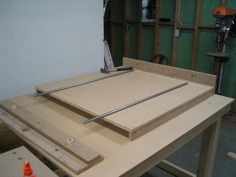
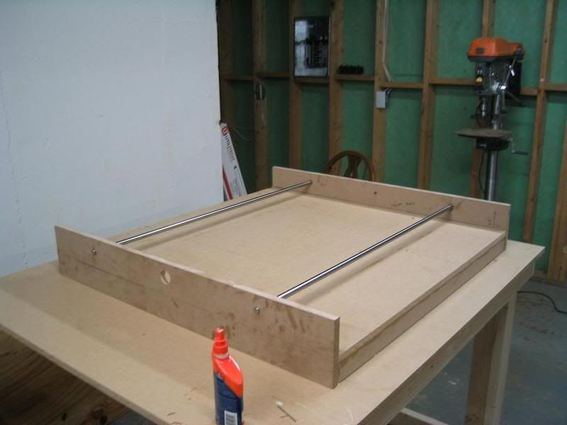
Here's a list of specs:
-Material used is 3/4" MDF
-I'm using a HobbyCNC controller with 305 oz-in steppers
-I'm hoping to cut mainly wood and plastic, and maybe try aluminum.
-The guide shafts are 5/8" diameter.
-I'm using PTFE linear bearings, since they are cheap, I figured I could just upgrade if they didn't perform well. (so far they seem okay)
-I bought a porter cable router, but I think it will be too heavy for the machine, so I'm probably going to using a dremel instead
-The Z-axis has not been designed yet.
-The platform (for the workpiece) has not been assembled yet.
-I'm using 1/2 - 10 precision acme rod
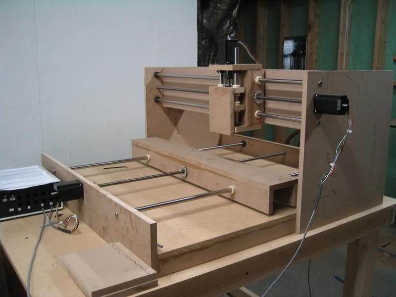
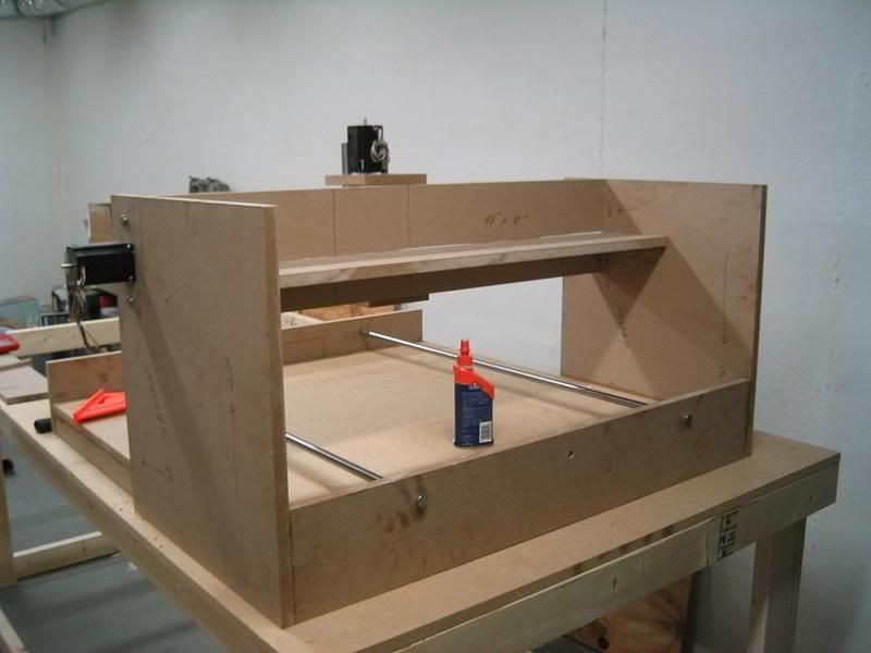
-I don't have exact numbers for travel, but its roughly 36" x 36" x 4". The overall dimension of the machine is 41.5" x 41.5"
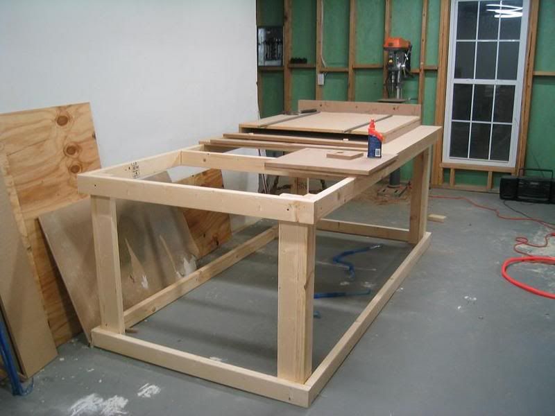
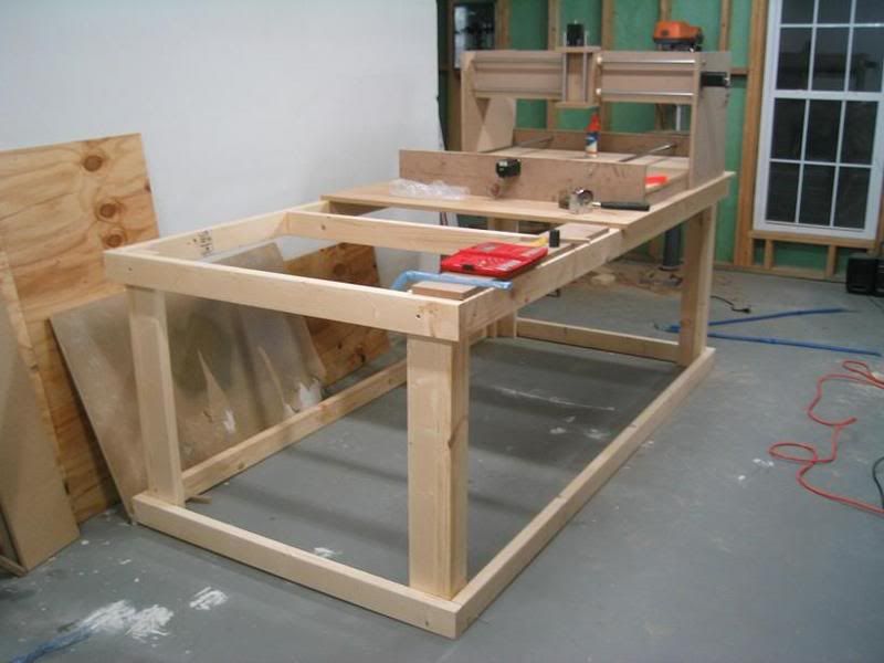
What do you guys think? Overall it seems pretty sturdy. I'm using wood glue and nails to secure the thing together. The thing is so big I had to build its own table. The table is 4' x 8', I tried to make it big enough to also support a desktop computer.
-Levino
Results 1 to 20 of 34
-
10-19-2007, 04:37 AM #1
 Registered
- Join Date
- Mar 2007
- Posts
- 18
Router Using 3/4" MDF (first router build)
-
10-19-2007, 12:58 PM #2
Member
- Join Date
- Apr 2007
- Posts
- 8082
eguy208,
Your machine is looking good. No problems that I can see so far.
I think that you will find that a Dremel tool shaft bearing flexes the plastic housing too much under heavy side loads and will cause chatter. Mine does when just using their router base attachments. Lots of people use the Dremels though. For fine detail work where small cutter bits are needed and speed isn't a factor the Dremel will work fine.
You can swap out the plastic bushings for bronze bushings, or you can modify the z axis assembly to install linear bearing blocks on the shafts. If the Porter Cable router is heavy enough to cause flexing in the y axis shafts near mid span, then something lighter like a trim router can be used.
CarveOneCarveOne
http://www.carveonecncwoodcraft.com
-
10-19-2007, 02:55 PM #3
Member
- Join Date
- Sep 2003
- Posts
- 1472

Hi Eguy,
There may be a couple of potential problems with this design. I made the same mistake when I made the first version of my CNC.
The guide rods are not supported, you will be surprised how little weight it takes to deflect this metal, and the defelection will change from the center to the ends.
I notice your guide rails do not have a means of adjustment on the ends, no matter how hard you try and bore the guide rod mounting holes perfectly it is almost impossible to get them perfect, this will cause excess drag if they are out of alignment in any direction with these type bearings.
Don't give up, it is a fun project but there are certain rules that are hard to bend.
Hager
-
10-19-2007, 03:39 PM #4
Registered
- Join Date
- Mar 2007
- Posts
- 18
Yeah, I can tell the shafts are deflecting when I push on them. I was hoping it wouldn't cause too much trouble for me. When I get to the point were I'm needing fine detail, I think I'll be able to swap the lower guides out for supported shaft, that way I don't have to build a new machine. The deflection is also in the Y-axis, is it okay to use the supported shaft there as well? Or will the bearing not like being mounted sideways? Originally Posted by Mr.Chips

As far as shaft alignment, I haven't made those alignment blocks yet. I drilled the holes just big enough to slide the rods in and mount things up. I can tell there is a slight misalignment. My fix for now was to bore the holes bigger until the shafts weren't binding, and then add the alignment blocks.
Thanks for the comments, this is definitely a fun project that look forward to advancing.
-Levino
-
10-19-2007, 05:50 PM #5
Member
- Join Date
- Apr 2007
- Posts
- 1955
Nice start on a project - already further along than I am.
I am not sure about nails and MDF and vibration. Maybe screws would be more resistant to pulling out ? I assume the nails are there to hold it while the glue dries, which might be ok as well.
-
10-19-2007, 05:58 PM #6
Registered
- Join Date
- Mar 2007
- Posts
- 18
Yes, all pieces are held together with carpenter's glue. The nails may provide extra strength, but mainly it allows me to keep working on the machine without having to wait for it to dry. Originally Posted by harryn
I'll probably add some screws later on just to be sure.
-Levino
-
10-19-2007, 10:50 PM #7
Registered
- Join Date
- Apr 2007
- Posts
- 323
on useing a dremel..i was wanting to use a drimmel also..but was thinking of making a mount to remove the internals "the motor" taking all the plastic off the drimmel and replacing it with an aluminum "case"sort of mount them in a solid aluminum block this would make it super ridged i think....still just a thought nice looking build so far ,any reason you want a moving table vs. a moving gantry? (im still in the designing stage)
"witty comment"
-
10-20-2007, 08:20 PM #8
Registered
- Join Date
- Mar 2007
- Posts
- 18
I figured the less mass the steppers have to move, the easier it will be it making a sturdy structure. I'm sure you can see, moving the gantry would have been more mass then moving the workpiece. Originally Posted by .xXACEXx.
A downside that I knew of, is the machine will need room to move it's X-axis. My next machine will mostly likely have a moving gantry.
-Levino
-
10-20-2007, 08:35 PM #9
Member
- Join Date
- Sep 2003
- Posts
- 1472
Moving Gantry Vs Table
It is much easier to make a non moving gantry much more solid than a moving gantry. That is for the typical hobbist that doesn't have access to a machine shop full of equipment.
It is I guess cheaper also to build.
My 2 cents worth.
-
10-20-2007, 09:09 PM #10
Member
- Join Date
- Oct 2005
- Posts
- 4230
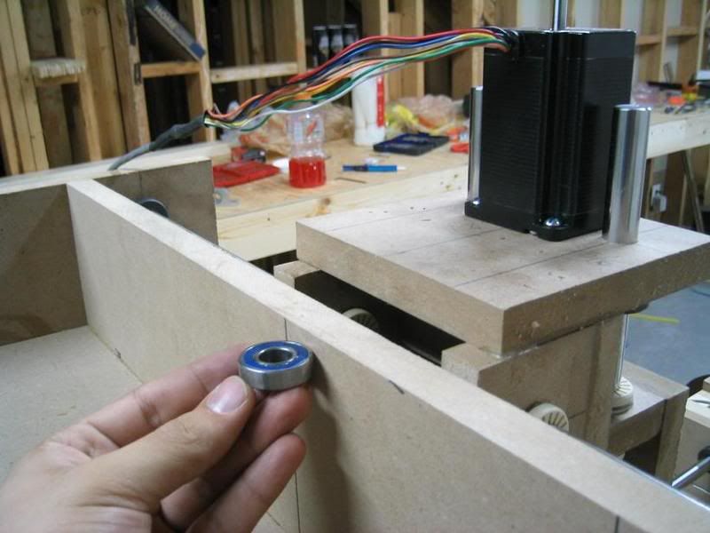
i tryed the same thing on my first setup but the weight of the gantry was too much for the rail so i cut some mdf and slid it under the rails on the x axis for support and used the skate bearing design , it made all the difference in the world , it would be a simple and effective mod for you at this point of the game Originally Posted by eguy208
you can see what i mean in the pics
http://www.cnczone.com/forums/showthread.php?t=20494
-
10-21-2007, 01:30 AM #11
Registered
- Join Date
- Sep 2007
- Posts
- 740
Some have substituted a Proxon for the Dremel. I have no experience, but have not seen negative comments on this subistute.
-
10-22-2007, 04:33 AM #12
Registered
- Join Date
- Mar 2007
- Posts
- 18
Made a little progress. I've got the acme rods installed (not the nuts though). I'm using shaft couplers to mount them to the motors. The workpiece platform is just laid in the machine and not mounted yet....it will be removable.
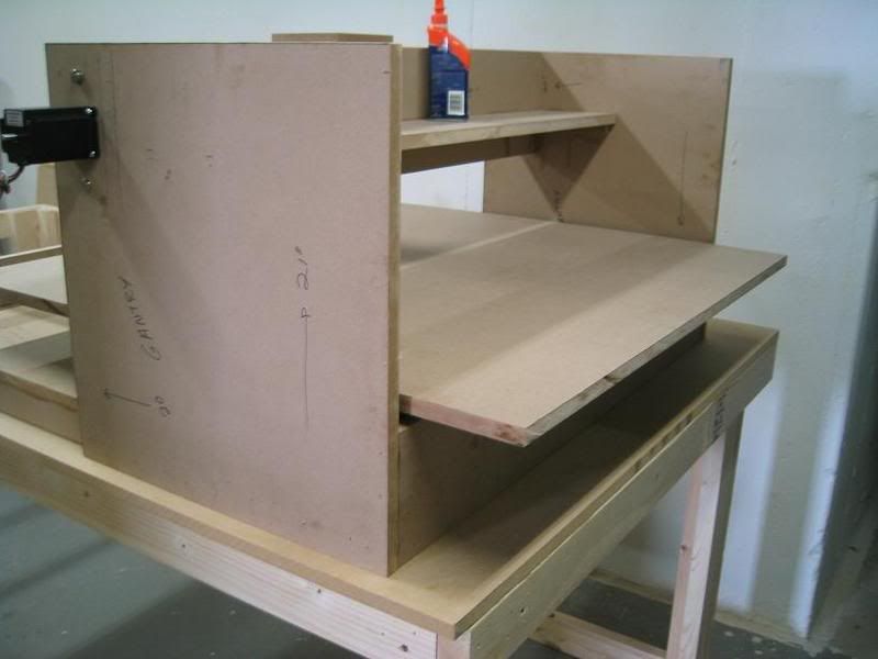
The MDF got chewed-up when making the motor mount hole. I didn't use clamps and the wood began vibrating and chewed up the hole. It still works, just looks like crap.
-Levino
-
10-22-2007, 01:58 PM #13
Registered
- Join Date
- Mar 2007
- Posts
- 18
Cool, thanks for the tip! Originally Posted by dertsap
-Levino
-
10-23-2007, 04:40 AM #14
Registered
- Join Date
- Mar 2007
- Posts
- 18
Can I find off the shelf adjustable guide rail mounts. Something like what this guy is using (the metal block with 4 bolts that allow the guide rails to be adjusted)
I could probably make them, but I'd rather put my time into other parts.
-Levino
-
10-25-2007, 03:43 AM #15
Registered
- Join Date
- Mar 2007
- Posts
- 18
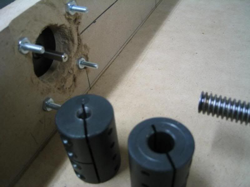
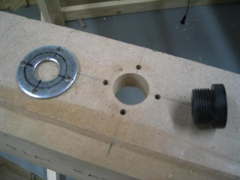
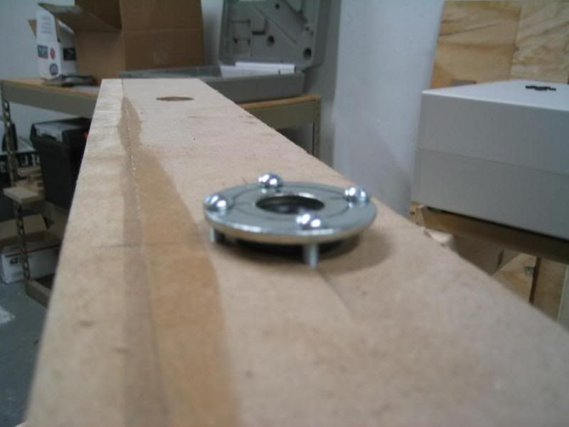
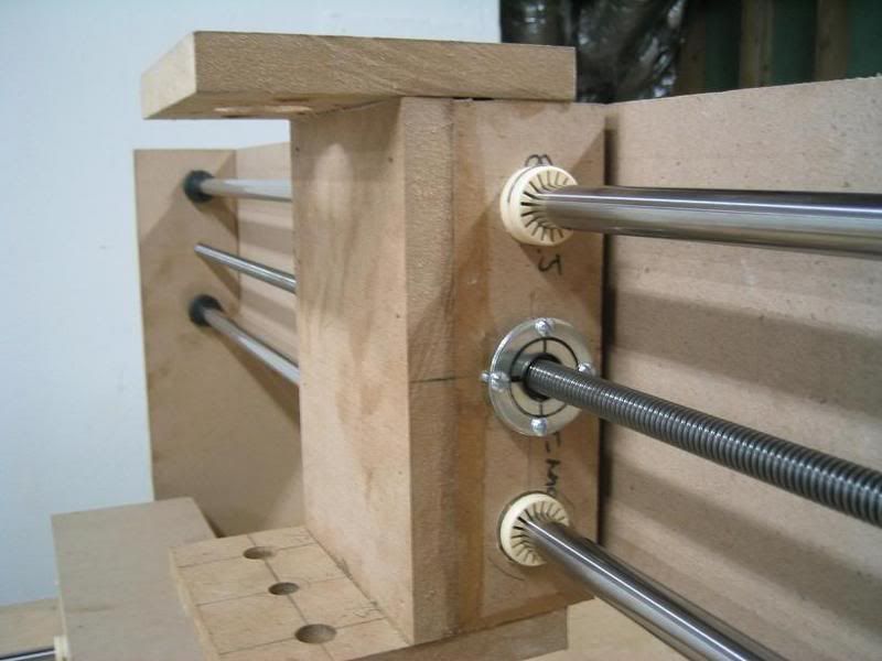
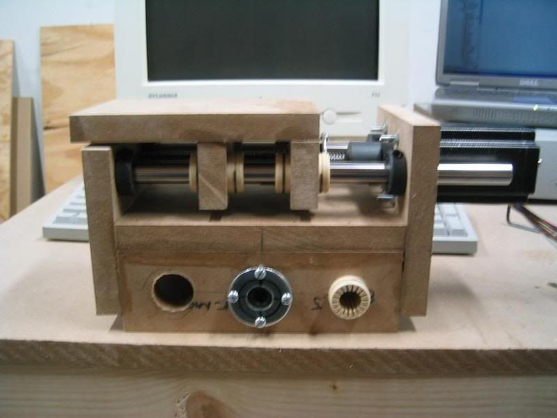
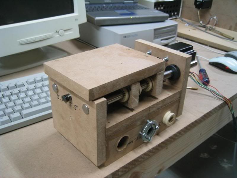
The acme hardware is finally installed. I used "Precision Acme Rods" instead of "Precision Modified Acme Rod". Precision Modified Rod is a lot more expensive. Because of this I had a crappy selection of Acme nuts, none of them had flanges, so I had to make a clamping flange from a washer.....turned out pretty good.
Here's the acme nut (black), hole and washer:
Installed nut using 4 screws and washer:
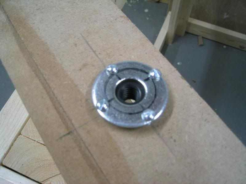
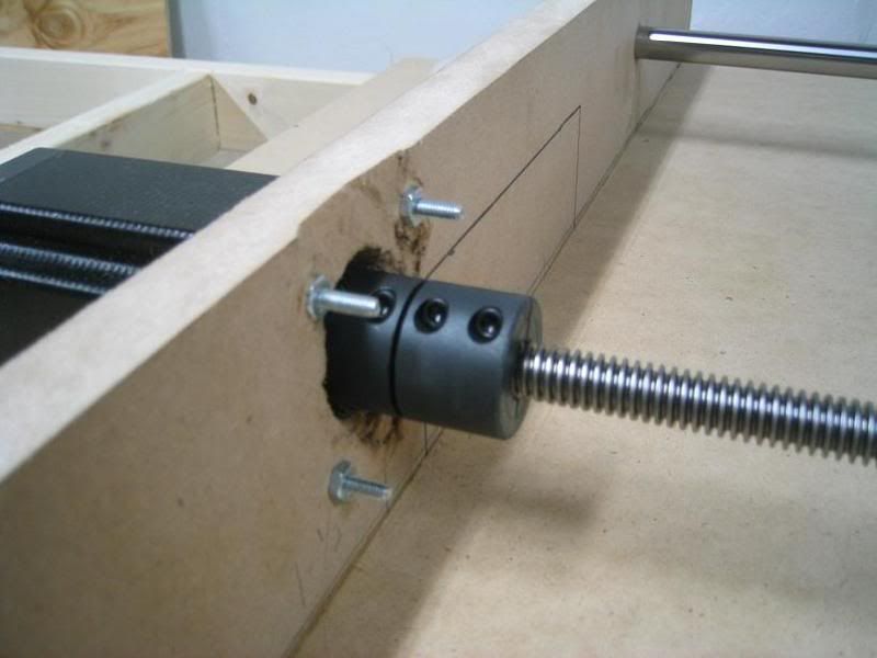
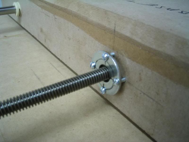
Installed on machine, X and Y axis:
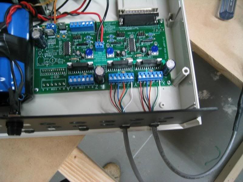
For a controller, I'm using the 3-axis kit from www.hobbycnc.com.
Here's the motors wired up, I don't have the Z-axis wired up yet:
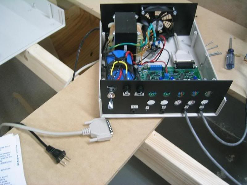
I might need to purchase a desktop computer. I don't have a 25 pin plug on my laptop, so I'm reduced to using a usb => 25 pin adapter. I'm guessing if there's too much lag in the adapter, the machine won't work properly.
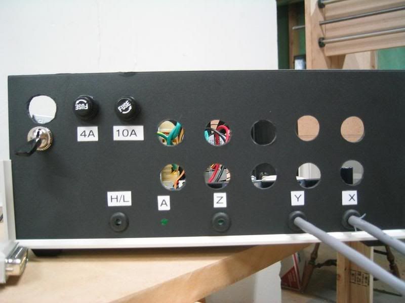
Here's the front of the unit:
-Levino
-
10-27-2007, 07:59 PM #16
Registered
- Join Date
- Sep 2006
- Posts
- 28
you will propably need to buy a desktop computer, CNC does not work through the USB->Paralell adapters, but there is a quite expensive PCMCIA card that have a paralell port that CNC control works with...
-
10-30-2007, 03:50 AM #17
Registered
- Join Date
- Mar 2007
- Posts
- 18
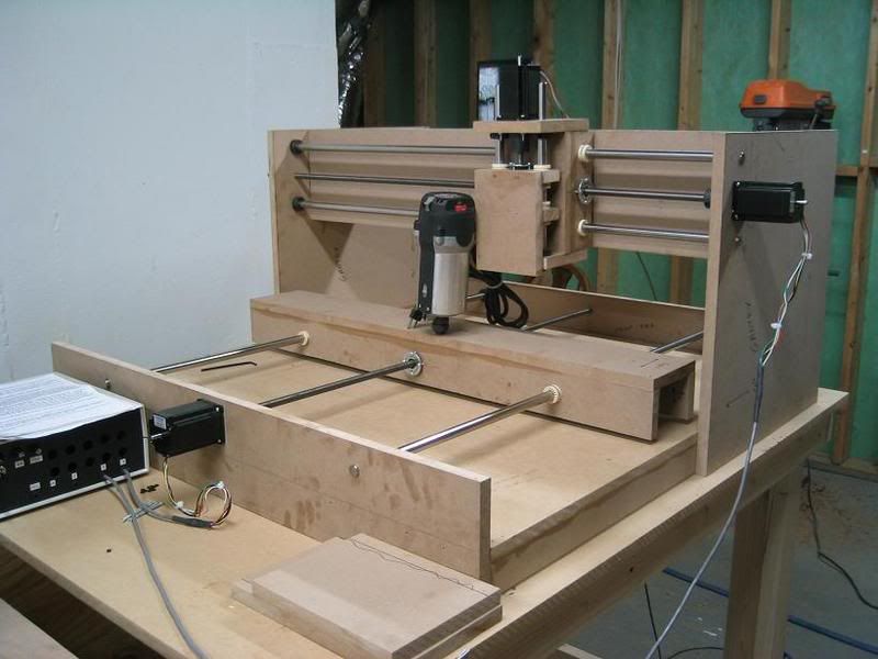
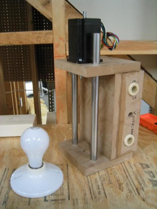
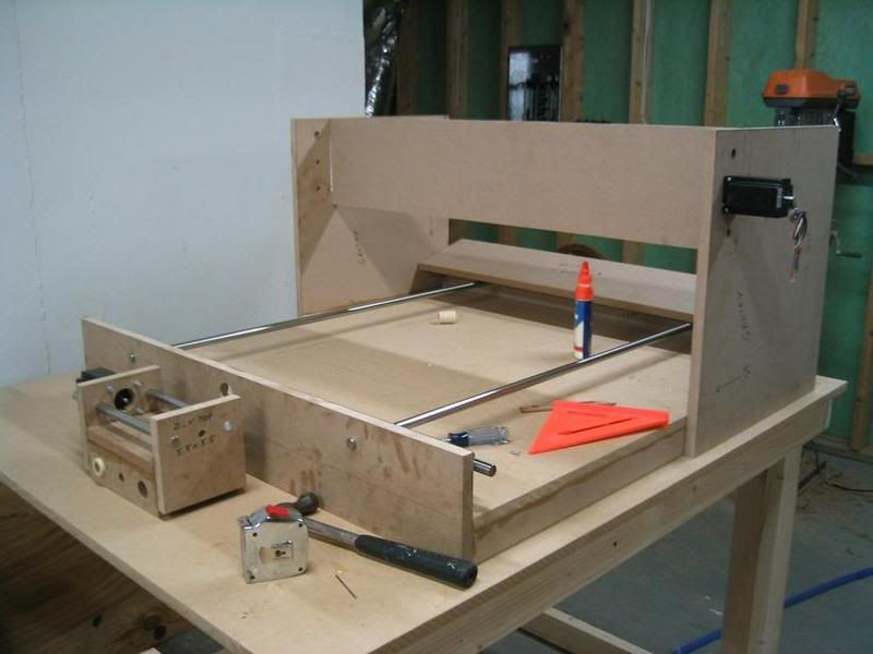
Okay, here's a little progress. I finally worked on the Z-axis. Here is the finished Z-axis (one bearing isn't installed). I should have ~3.5" of travel. I need to move those shaft collars to the outside of the wood to get the full 3.5":
I bought a porter cable router off ebay a while back:
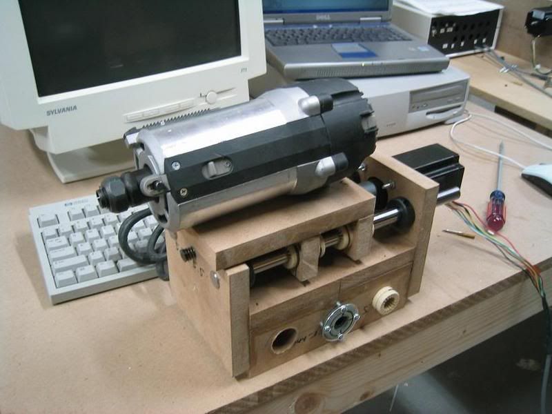
I'm waiting for the mount in the mail, should arrive by the end of the week. I got the K2 mount:


Here's the Z-axis on the gantry:
And the motor for size comparison:
Also me holding the motor:
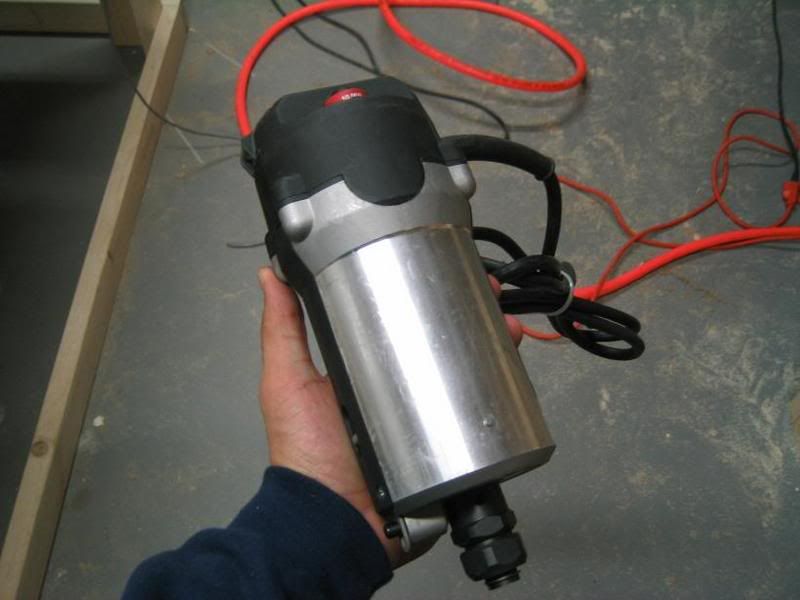
The motor weighs 8-10 pounds, so it causes the Y-axis guides to deflect a little too much. To discourage this, I want to incorporate a L-bracket that hooks to the back of the Y-axis, and use bearings to decrease friction:

I don't know exactly how I'm going to go about it, but if I can't mount the big motor, I'm going to have to use a dremel instead.....which would suck.
As soon as I get the motor mounted, I'll only need to get the computer stuff figured out and I can then begin cutting stuff :biggrin:
-Levino
-
10-30-2007, 05:11 AM #18
Gold Member
- Join Date
- Jul 2003
- Posts
- 162
The real deflection problem will be in the other direction. When you start plunging the Z will tilt back a lot more than just the weight of the router tilting it forward.
-
10-30-2007, 05:16 AM #19
Registered
- Join Date
- Mar 2007
- Posts
- 18
Ha, didn't even think about that. Cool thanks! I'll see if I can come up with a solution that makes it rigid in both directions Originally Posted by Rhodan
-Levino
-
10-31-2007, 06:24 AM #20
Gold Member
- Join Date
- Jul 2003
- Posts
- 162
Have you thought of putting the bearings into the back of your Y carriage? This just popped into my head - might be totally useless but its a thought.


 Reply With Quote
Similar Threads
-
building a cnc router
By TheCrazzyman in forum Mechanical Calculations/Engineering DesignReplies: 3Last Post: 10-06-2006, 06:05 PM -
building first cnc router
By bradyfb in forum DIY CNC Router Table MachinesReplies: 0Last Post: 11-02-2005, 02:38 AM -
5' x 10' router building need help
By stevelang in forum DIY CNC Router Table MachinesReplies: 13Last Post: 08-29-2005, 06:55 PM -
Building My First Router
By CAMmando in forum DIY CNC Router Table MachinesReplies: 27Last Post: 08-03-2003, 06:19 PM
