


Nice work on the conversion!! I hope I get my BP done soon, other projects are taking the money from the Bridge Port
Results 21 to 26 of 26
-
06-27-2007, 04:33 AM #21
 Registered
- Join Date
- Aug 2005
- Posts
- 828
Dennis
-
09-05-2007, 10:01 PM #22
Registered
- Join Date
- Apr 2006
- Posts
- 158
The pneumatic drawbar was a dismal failure. I had an estimated 1000 lbs of drawbar tension and I was still having the bits pull out on me.
So it looks like I am scrapping that idea. Might go with a system to use a gear motor to tighten/loosen the drawbar and use a small air cylinder on the brake.
Though about using a air ratchet like other drawbars but since I only need a few turns to tighten or loosen the drawbar I would have a hard time controlling the ratchet that closely.
My concern though is for the people that are buying the Z-Bot autochanger for the mini mill. I have more drawbar tension than they are using and am having pull out issues so I am sure this will be a problem on the Z-Bot.
-
10-24-2007, 01:36 AM #23
Registered
- Join Date
- Mar 2007
- Posts
- 24
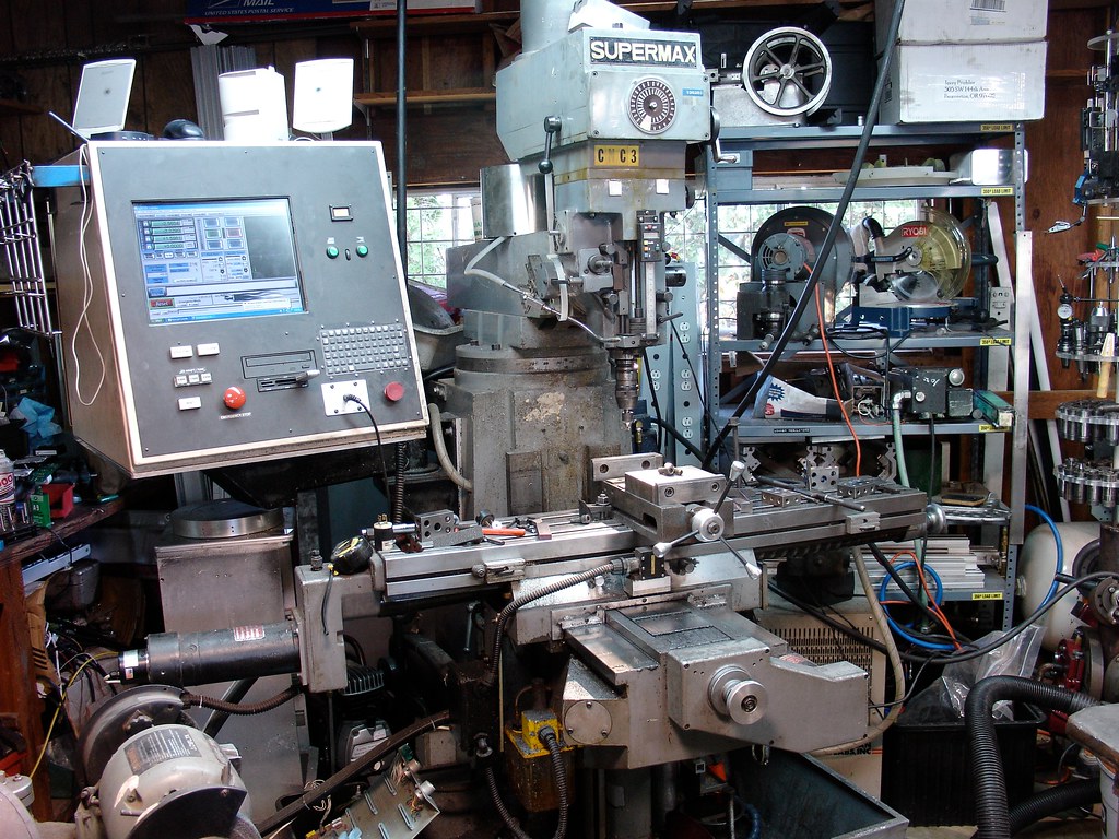
supermax ycm 30
Wow, this is an excelent looking project. Im am impressed. I need to get more details on how you utilized the glentek servo drivers and hooked up pixies or G-rex. I dont know anything about what the pixies or the g-rex do. I am supposed to retrofit my friends 1987 model supermacx ycm 30 and for payment he will give me a series one boss 1 or 2? bridgeport.
The supermax machine looks brand new and the only thing wrong with it is that the controler lost memory and all parameters. I want to hook up a pc with mach 3 or EMC to talk to the glentek servo drives. What is your best reccomendation for a plan of action after you have retrofited a very similar machine. I have a VFD to run the spindle on and can easily rewire the rest of the machine to run on 1 phase 220.
-
07-11-2011, 07:28 AM #24
Registered
- Join Date
- Apr 2006
- Posts
- 158
Its been about 5 years now and its been a good mill. A few little quirks. If you powered up the servos with the drives enabled it would jump and sometimes fault out or trip one of the breakers inside of the control for the drives. This was caused by the Pixie step/direction to analog control boards. These boards would take step and direction inputs and control standard analog servo drives with encoder feedback. They worked pretty well, but tuning was a nightmare. Not only did you have to tuned the analog drives, you also had to tune the position loop. It had some decent gui software but I really never got it tuned like it should. I would get random follow error trips when the machine changed direction.
Rather annoying. That and the X axis motor is rather long and I dont know how many time I have ran into it.
With this last week being a production break from Paranorman I figured I would finally have some time to do something about these problems. A couple years ago I got that Mitsubishi injection molder. Among the servos on it were two Mitsubishi MR-H series 1kw servo drives and motors. I also had another Mitsubishi 1.5kw MR-J series drive and motor from back when I was gearing up to do the servo retrofit on my 10EE. The 1kw motors were much smaller than the old ones and about 5" square. The 1.5 is a touch bigger than the old motor. Both models of drives have step and direction input native.
In anticipation of doing this project I had machined adapter plates and motor mounts for the motors ahead of time. I also hand some small circuit boards made up through the dorkbotpdx circuit board service. These boards broke out the 40 pin MDR connector to give me easy access to the step, direction, and alarm out lines.
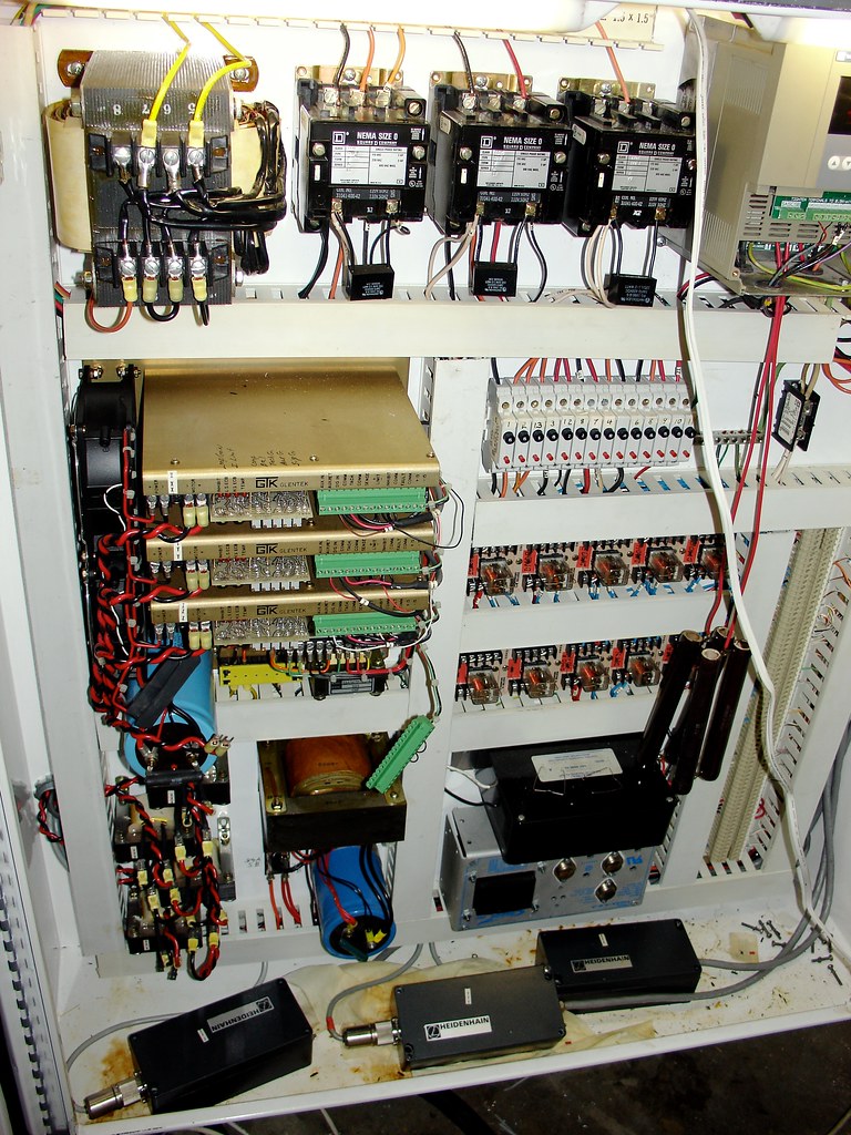
This is what it looked like after the first retrofit. The gold parts in the control box are the servo drives, the main power transformer up top, aux transformer below that ran the old control, chokes below the drives. Also three contactors that controlled coolant, servo power, and a spare. The three Heidenhain boxes on the bottom are interpolators for the linear scales it had mounted for feedback on the original control. I initially tried to used the scaler but the performance was terrible.
DSC03386.JPG by macona, on Flickr
DSC02756.JPG by macona, on Flickr
DSC02758.JPG by macona, on Flickr
-
07-11-2011, 07:29 AM #25
Registered
- Join Date
- Apr 2006
- Posts
- 158
Wednesday night I decided to dig in. My goal was to finish it by sunday as I need it for work this week. I put it on rollers and slid it away from the wall.
Thursday I gutted the machine. Pulled out anything to do with the servos, transformers, drives, scales, contactors. Yanked of the servos and pulled off the pulleys. Bored out the pulleys to 24mm and broached a 8mm keyway for the motors.
Y axis motor installed without a hitch. Did have to use a rotary file to remove a little more of the motor mount casting but I expected that. It bolted right into place. The Z motor was similar. Mounted in place of the old one. The X axis was a little more painful, literally, I managed to get myself really nice like while trying to get the pulley off. Since the new motors have a larger face on them I had to mount the X axis to the sides of the casting.
Friday I did the motor and encoder wiring. Ran all over town to try and find the wire I wanted, ended up getting stuck with MTW. The machine has sealed cable carriers and I managed to get the new motor cables and encoder cables in them to the control box. The Z axis encoder had to go externally. It was just too fat to fit through the conduit.
Saturday I mounted the drives and support pieces. I wired in mains power to the drives breakers, contactors, and finally to the drives. The newer drives control the buss power and shut it down if there is a fault. I finished the connections to the motors and encoders. The Z axis encoder amphenol was a pain. Must have been about twenty wires. Differential A,B,Z plus hall tracks for UVW. X wasnt so bad, by that time they went to a serial interface encoder and there are only a handful of wires. I tied the motors into the drives and the encoder cables as well. I got initial power to the Z drive and was able to jog the motor from the test mode.
Originally the machine was ran off 4 wire 208 so it had 120v off the lines. I did a no-no and was using the ground as a neutral. With the extra space I installed a .5kva 240 to 120v control transformer to run the computer, contactors, and lube pump.
That night I also got the cables ready. I reused the drive cables that came out of the molder. They have 50 pin MDR connectors on one size and 40 on the other. I took one of the cables and put the 36 pin connector for the MR-J drive on the end for the Z axis. While doing this I found a mistake on the board. So I cut that trace and jumped to correct it.
So, finally, this morning I did the control wiring. I needed to mount the interface boards. For some reason I neglected to put in mounting holes so I had to add those. I too a piece of 3/8" white PVC sheet and made a plate to mount the three boards to. This mounted next to the drives. I wired up the contactors and estop interlock for the drives.
I went into the computer cabinet and yanked out the old pixie boards. I reused the analog signal wires for step and direction signals.
Finally it was time to make it move. Powered everything up, grabbed the pendant, and turned it. Nothing. Huh. Eventually after some probing I found I had mislabeled the silkscreening on the interface boards. I connected the signal wires to the correct spots and X and Y moved! But Z didnt. On the newer drives you can enable the drive in the parameters. I had forgotten that the old drives have to be hard wired. Jumped that and still nothing. Oh yeah, left and right stroke inhibit. Jumped those. Now it moved.
But it moved very slowly with the native encoder resolution the X and Y were at 81920 pulses per inch. The Z axis was 64000 pulses per inch. I used the internal electronic gearing to divide those numbers by 8 on the X and Y and 5 on the Z. Much better.
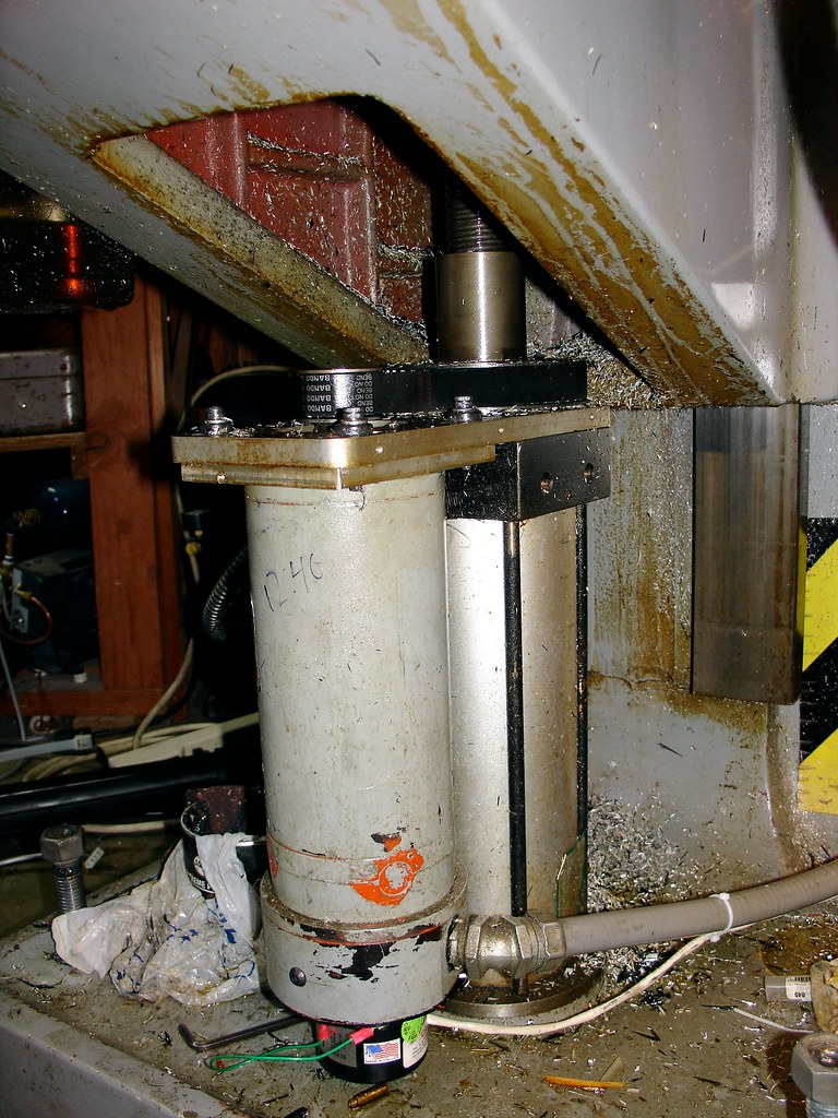
All while messing around with it I managed to get it to run through the Z bottom tie rods on the balance cylinder. The had been welded together from shorter screws. I repaired one, still need to do the other two. I also made a couple other mods, installed a SSR running off the computers 5v line to kill power to the servo contactors when the computer is off. Also tied the Z axis servo-on line to the e-stop loop. The older drives dont have a dedicated e-stop line like the newer ones.
So far it looks like it is going to work great. The Z (Knee) is a whole different creature now. Moves quick. I had to have the old motor's acceleration all the way down to 3 in/sec/sec. I can easily run the new motor at 50.

IMG_0939 by macona, on Flickr

IMG_0940 by macona, on Flickr

IMG_0941 by macona, on Flickr

IMG_0944 by macona, on Flickr
-
12-04-2011, 01:29 AM #26
Junior Member
- Join Date
- Nov 2008
- Posts
- 412
Nice Job!
Forget about global warming...Visualize using your turn signal!

 Reply With Quote