


Those boards all appear rather limited in their design from what little I could find out about them. You get what you pay for, if that, in this world!
Results 181 to 200 of 272
-
04-04-2010, 10:23 PM #181
 Registered
- Join Date
- Nov 2009
- Posts
- 113
-
04-04-2010, 10:37 PM #182
Member
- Join Date
- Dec 2009
- Posts
- 9
What more do you want? (Not to sound snarky, I don't know what other features people look for) Originally Posted by pfred2

(Now to sound a little snarky ) It seems to me that you are getting a lot more than you pay for, seeing as you get plans (something) for free (nothing).
-
04-05-2010, 03:27 AM #183
Registered
- Join Date
- Nov 2009
- Posts
- 113
Sharpening my Vorpal sword a little ...
Maybe more than 4 preset current limits? Who knows what else? information I saw is sketchy at best. One seller even admitted that advanced electronics knowledge was needed in order to implement the product because of rough information supplied!
Also there are a lot of knock off components that do not spec like name brand parts do. I'm not saying these boards come with those but then again no one can assure me that they don't either!
I just don't think there are a whole lot of merchants out there doing great charity work is all. They're in it for the money, so they're making it somehow.
I also have plenty of my own plans so I don't need anyone else's. I'm unique, just like everybody else!
"For the Snark was a Boojum, you see."
-
04-18-2010, 03:47 PM #184
Registered

- Join Date
- Apr 2006
- Posts
- 169
hi i fond thet
http://www.mikrocontroller.net/topic/161033

-
04-18-2010, 07:34 PM #185
Registered
- Join Date
- Nov 2009
- Posts
- 113
Like Vince the Sham-Wow! guy says, you know the Germans always make good stuff.
I need to get better sense resistors for my circuit. Though I found with a 120 pf Osc cap I can just about play a tune with a driver I made. I think the worst part of the TB6560 is the sense resistor setup.
Where has everyone been getting their sense resistors from?
-
04-19-2010, 05:50 AM #186
Erfahrener Benutzer
- Join Date
- Feb 2005
- Posts
- 122
Nice job. More than that I see that this guy it's using also Kicad (it's an open source EDA - and I'm a big fan of that too).
-
04-19-2010, 12:28 PM #187
Registered
- Join Date
- Nov 2009
- Posts
- 113
I tried to use kicad but it crashed on me early on trying to work through the tutorial. So its back to Eagle light for me! In a few years I'll give it another try. I also gave gEDA a try with similar results. Though I must say gEDA ran for a bit longer for me than kicad did.
I'm a little too busy working on my own project right now to deal with either of them.
-
04-21-2010, 09:43 PM #188
Registered
- Join Date
- Apr 2006
- Posts
- 169
Michael Schildt
http://www.mikrocontroller.net/attac...2010-04-19.zip
Hello,
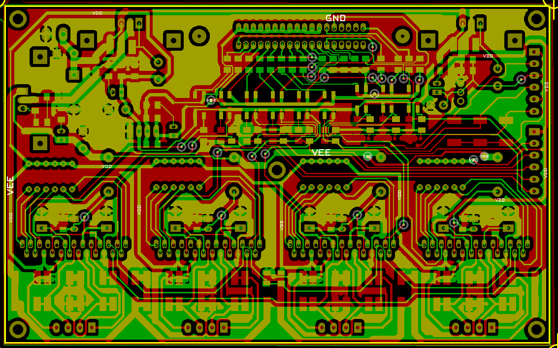
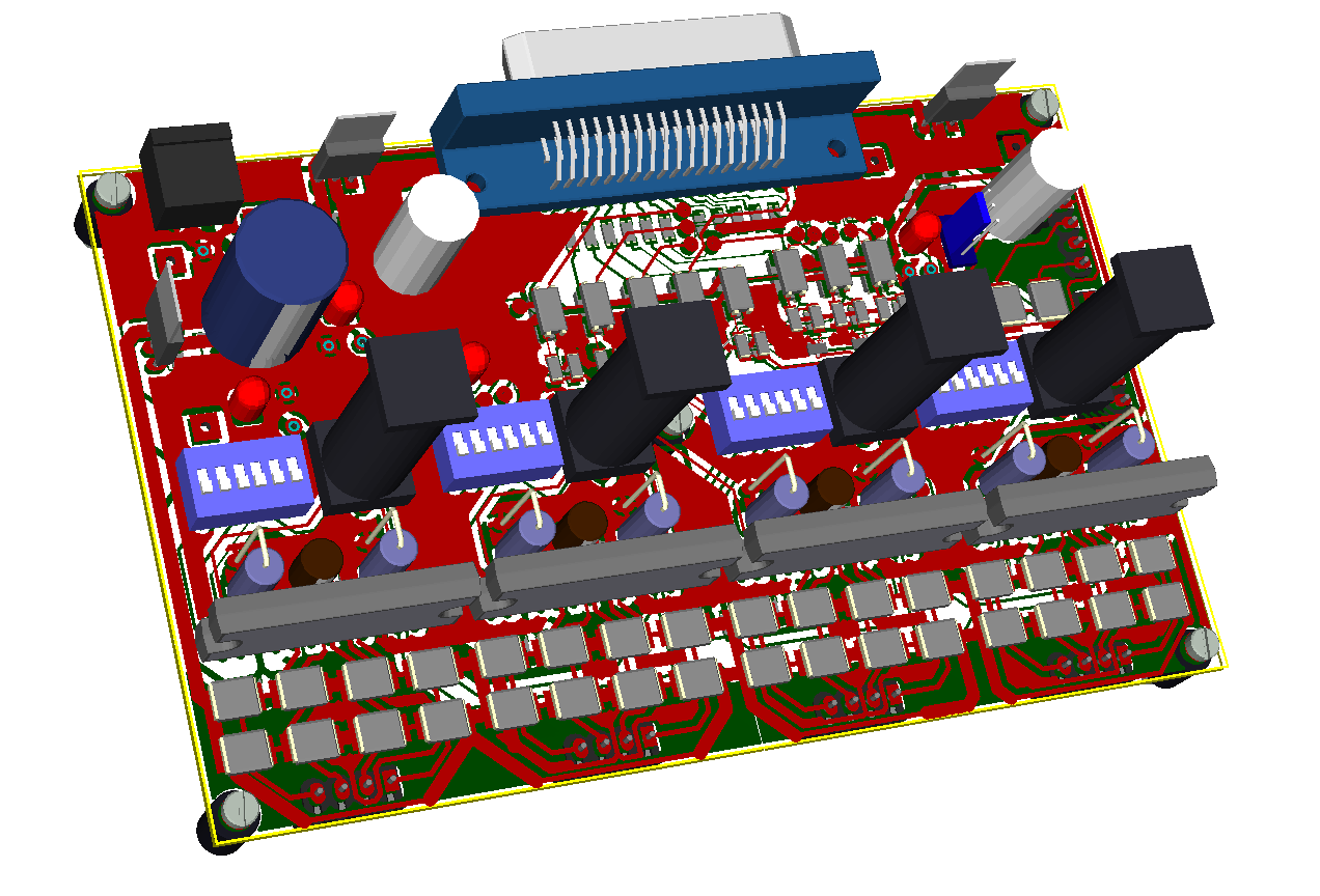
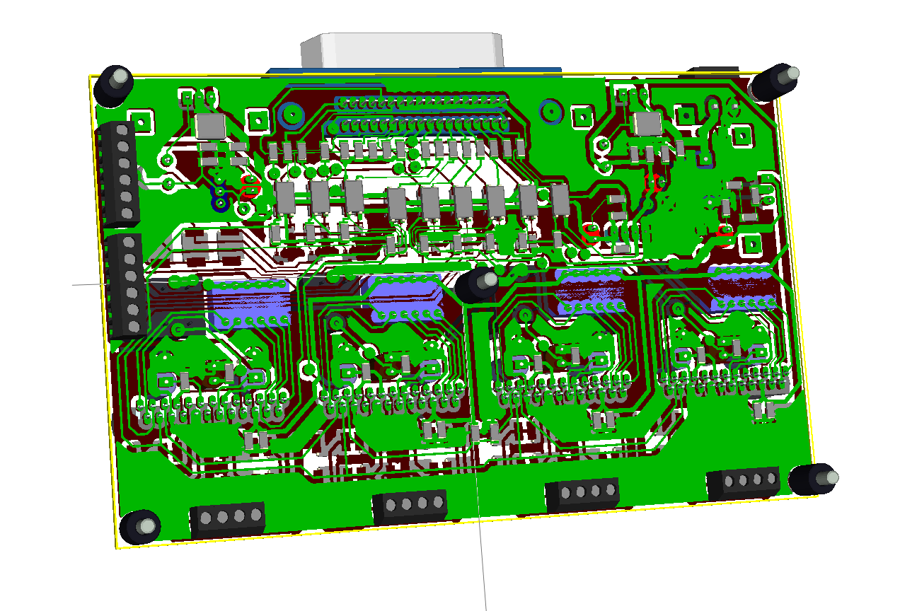
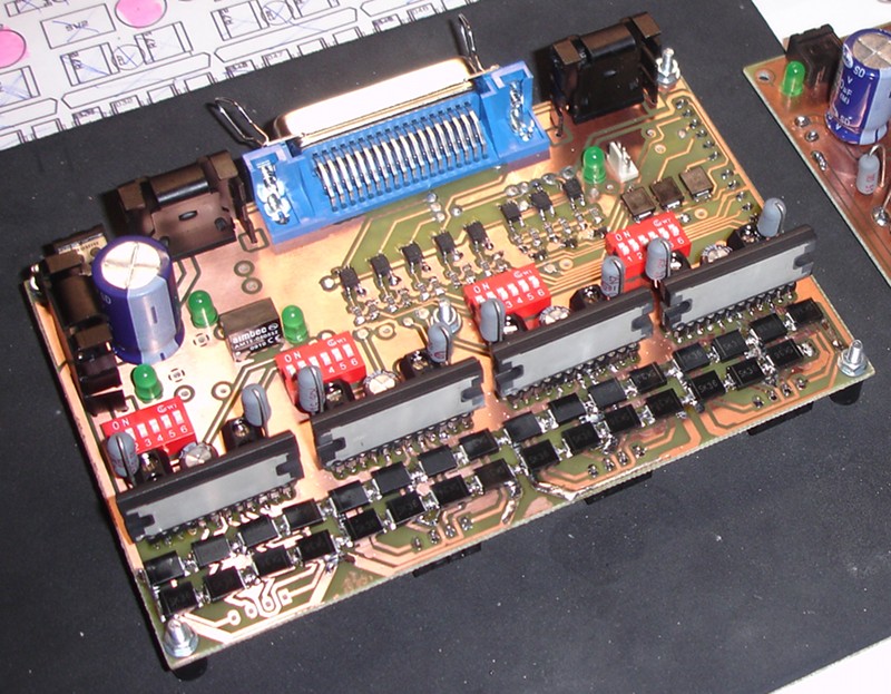
sure i share. Attached is an archieve of the project. It should contain
all neccesary data. By the way, version 2010-04-06 is out for KiCad.
Some remarks to the design:
- when building the pcb on your own, you need to take care for the
through connection and some parts needs to be soldered on both sides
(some pins on IC1-4, all pins on U1,U2 and Q8)
- the circuit works well with my Dell D600 Parallel port, but not with
the parallel port from the docking station, may be due to difference in
voltage, probably the hints of Pieter could help to solve this issue
- when the steppers hold, they make minimal buzzing sounds, but much
less than in the first version
- i used the circuit for some hours with this device
(http://www.cncecke.de/forum/showthread.php?t=51061) now and already cut
some wooden parts, the stepper are working smoothly
- and finally, i give no waranties in any way, since i'm an amateur in
this field
Ciao,
Michael
-
04-28-2010, 09:02 PM #189
Registered
- Join Date
- Apr 2010
- Posts
- 0
Greetings. I'm wondering if someone could give me a little help in choosing a driver. I'm building the basic 2' x 4' CNC from the Build Your Own CNC Machine book (mostly the same as the build at http://buildyourcnc.com/). I'm hoping to cut a bit of the expense of the project on the electronics, especially in the motor drivers and the PSU. Rather than buy a PSU I will probably wire 3 ATX PSUs together per instructions on these forums. So that will save me a bit.
As to the drivers, the build in the book recommends Keling KL-4030 drivers to drive the 425 oz-in bipolar steppers. Those drivers are $55 each and, like many, I got to searching and ran across the ebay auctions for TB6560 based 3+ axis drivers. After reading about the specs of these boards and the recommendation that most people have to keep them to 24 volts or less, I was ready to give up, since I'd like to stay at 36 volts (the initial build is going to use 1/2" 13 TPI threaded rod, so I'd like to keep some speed on these motors).
I'm still working through how stepper motors work, etc., but I thought I'd review the TB6560 datasheet and found that there are actually two versions of the TB6560: the TB6560HQ and the TB6560FG, with the TB6560HQ offering higher peak amperage (3.5 amps) and possibly some other differences? There appear to be other boards (besides the ebay boards) that use the TB6560, such as the one at cncgeeker here: http://www.cncgeeker.com/index.php?m...products_id=41 - it claims to be able to handle 40 volts, 3.5 amps.
I wonder if that is a fair claim? If so it might be a good choice to get up and running at 36 volts. If not, can anyone make a recommendation as to other options? What features, exactly, should I be looking for in a driver other than being able to handle the voltage and current of the motors? I understand number of steps is also important. Anything else?
Thanks for any suggestions!
-
04-28-2010, 09:56 PM #190
Registered
- Join Date
- Nov 2009
- Posts
- 113
I am running TB6560AHQ at 24 VDC and getting acceptable performance for me. Their fast decay mode really helps performance. subjectively fast decay is more like operating at close to double the power, as opposed to not using it. I'm getting usable torque at around 900 RPM. Just exactly how fast do you think you can spin a 4 foot length of 1/2-13 all thread before it whips anyways?
The differences between the two TB6560s is one, the package they come in, one is a through hole ZIP, the other is a surface mount QFP, and two the current rating, one is 3, the other is 2.5.
If you're running all thread you should just accept what you get. Your motor drivers are the least of your concerns! A twin start 5 TPI lead would give you almost 3 times the rapid speed right there. So lets just forget about pushing the outer boundaries of a poor IC shall we?
Absolute maximum ratings should not be used as operating parameters. Typical good engineering in electronics assumes 50% margins for safety, and reliability. At best you will have much shorter device life, at worse total device failure. Also, absolute maximum ratings are assumed applicable to a median sampling of devices. It is a guideline that you, and others seem all too willing to ignore though.
Then again, I guess you could get some super devices too, that'd do it no sweat. I think you have a better chance buying a winning lottery ticket than expecting devices to operate at their maximum for too long. But that's just me, but then again I don't expect a gourmet meal when I walk into a fast food joint either.
I'm also not sitting here crying over blown up electronics, like I've seen so many others do.
-
04-28-2010, 10:37 PM #191
Gold Member


- Join Date
- Feb 2007
- Posts
- 4553

Is anyone selling just the bare PCB board for the four axis TB6560AHQ?
Jeff...Patience and perseverance have a magical effect before which difficulties disappear and obstacles vanish.
-
04-28-2010, 11:23 PM #192
Registered
- Join Date
- Nov 2009
- Posts
- 113
I cannot imagine why. PCBs are designed for specific parts and by the time you got done chasing down every last one you need you'd end up spending a lot more than they do buying in quantity. Just look for the non-inductive current sense resistors TB6560s use. Good luck getting those in small quantities cheaply.
I found just the thing at Digi-Key, too bad they're $1.90 a piece. Plus, if you're going to go through all the troubles of putting a board together whats to designing one exactly how you want it?
There are places that make boards. Of course I'm saying all of this while I point to point wire up yet another stepper driver board here. Ha-ha!
http://img697.imageshack.us/img697/7711/pict0789w.jpg
http://img717.imageshack.us/img717/8530/pict0787a.jpg
Just now working on my first TB6560AHQ based board, so no pictures of it quite yet. When I get my CNC machine done I'll etch, but for now this will have to do. And it does too, work that is. Though doing it my way is even harder than it looks.
-
04-29-2010, 01:24 AM #193
Gold Member
- Join Date
- Feb 2007
- Posts
- 4553

Pfred2,
I have about a 100 of the TB6560AHQ chips, otherwise I would not bother.
If you find a ready made board like the one "Hesham Morsy" posted please let me know.
Jeff...Patience and perseverance have a magical effect before which difficulties disappear and obstacles vanish.
-
04-29-2010, 02:10 AM #194
Registered
- Join Date
- Nov 2009
- Posts
- 113
Maybe you missed the part where the sense resistors can cost almost as much as the ICs themselves?
Possibly you have more than you need and can sell off some and get what you want?
-
04-29-2010, 06:02 AM #195
Gold Member
- Join Date
- Feb 2007
- Posts
- 4553

Pfred2,
In quantity the resistors cost about six cents each.
http://tinyurl.com/2aqxrq5
How about Three .18 ohm 2 watt resistors?
http://tinyurl.com/258s7fv
Jeff...Patience and perseverance have a magical effect before which difficulties disappear and obstacles vanish.
-
04-29-2010, 12:46 PM #196
Registered
- Join Date
- Nov 2009
- Posts
- 113
For my application I need .25 ohm and through hole. That, and about a dozen is all I really need.
These would work:
http://search.digikey.com/scripts/Dk...me=15FR250E-ND
-
04-29-2010, 07:21 PM #197
Registered
- Join Date
- Feb 2009
- Posts
- 40
There seems to be another 3 axis single sided PCB for this chip -
http://rchobby-net.de/fraese/tb6560ahq/tb6560.htm
http://rchobby-net.de/fraese/index.htm
Someone is doing a 1 axis board in Eagle -
http://samroesch.blogspot.com/2010/0...ed-tb6560.html
-
04-29-2010, 09:52 PM #198
Gold Member
- Join Date
- Jun 2003
- Posts
- 3312
The 40volts is the max rating and that would include BEMF which is additive to the power supply voltage, and any transients from design and pcb layout. Without protection a 36V power supply is not advisable. Originally Posted by theminor
Phil, Still too many interests, too many projects, and not enough time!!!!!!!!
Vist my websites - http://pminmo.com & http://millpcbs.com
-
04-30-2010, 01:56 PM #199
Registered
- Join Date
- Nov 2009
- Posts
- 113
I can't tell exactly what they're doing but there do appear to be, in the picture, diodes the motor outputs are connected through on the board. While the claims may be a bit inflated it looks like a really nice board for the price to me. I'd love to hear from others their experiences with it, or similar products. One thing I am not seeing is decoupling capacitors on the boards like Toshiba recommends used. Sure there may be some, but if thats them then they're poorly placed. Or maybe there are components mounted on the backside of the board? Anyhow, if it works at all then it may be one of the best values around. $23 and change to drive an axis is hard to beat!The 40volts is the max rating and that would include BEMF which is additive to the power supply voltage, and any transients from design and pcb layout. Without protection a 36V power supply is not advisable.
I have to admit, I have my reservations about it. I'm not hitting the buy button on it. If my situation was different though I might be tempted.
-
06-29-2010, 10:29 PM #200
Registered
- Join Date
- Jun 2010
- Posts
- 0
Hi all!
That's my firs day here, I just spent some time reading this thred so I can collect as much info I can. grate team here! :-)
I'm planning to build a TB6560HQ based controller but as I can see there is no final and no best solution yet born. Or did I missed soemthing?
pminmo, I'm curious to see your version too but unlikley I'm not using Eagle. I downloaded your schematics from your site and I'm not able to import it in Altium. Are you ablle to export it in any other format or in a worst case could you just post it as a jpg or pdf?
Thanks!

 Reply With Quote
Similar Threads
-
THB6064H(4.5A)-Stepping Motor Driver IC 4.5amp
By NASR1 in forum Open Source Controller BoardsReplies: 184Last Post: 10-03-2014, 12:52 AM -
Stepping Motor Driver IC THB6064H
By lihaijiang in forum Engraving MachinesReplies: 0Last Post: 07-07-2009, 03:49 AM -
THB6064H stepping Motor Driver IC4.5A
By lihaijiang in forum News AnnouncementsReplies: 0Last Post: 06-22-2009, 03:29 AM -
Stepping Motor Driver
By MR MOTION in forum Stepper Motors / DrivesReplies: 2Last Post: 05-17-2009, 06:13 PM -
80V 6A Micro stepping Motor driver
By eded59 in forum Stepper Motors / DrivesReplies: 0Last Post: 07-31-2007, 03:43 AM
