


I have a nice Fagor DRO that I bought for a lathe that I wanted to mount on my mill in order to map my ballscrews. It is supposed to be accurate to 0.0002", so it should be a nice reference for calibrating this mill.
First job was to make brackets. Very easy with the Mach3 wizards, especially the Newfangled Wizard. Here is the reader head bracket for the scale on the X-axis:
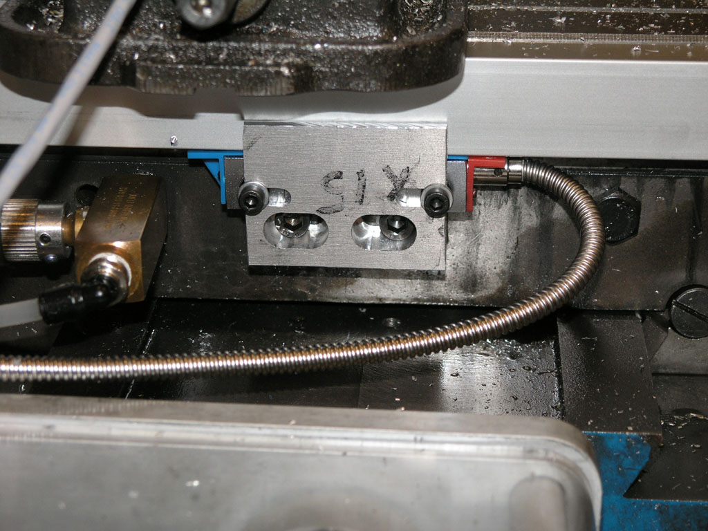
The reader head mounts where the home/limit switch goes. The DRO is only temporary and I didn't want to make any new holes in my mill! Note how the bracket protects the head a bit...
Each end of the scale is held by a little L-shaped bracket. You need to be able to tram the DRO scale in so it is level and square with the table...
And here is the control panel for the DRO...
Results 1 to 11 of 11
-
05-31-2009, 06:27 AM #1
 Gold Member
- Join Date
- May 2005
- Posts
- 2502
Using a DRO to map your ballscrews
-
05-31-2009, 06:31 AM #2
Gold Member
- Join Date
- May 2005
- Posts
- 2502
The bracket was very easy to make using the CNC Wizards in Mach3, and especially the Newfangled Wizard. Here are some pix of the construction of the reader head bracket:


Love my 5/8" Helimill. Those APKT inserts cut through aluminum like butter!
I thought I'd map my X ballscrew just to check its accuracy with the DRO. Here is what I found with a series of half inch jogs:

The left axis shows the actual move of each commanded 0.5000" move as measured by the DRO. If the ballscrew were perfectly accurate, the graph would be a straight line centered on 0.5000".
You can see the righthand 40% of the ballscrew is qutie a bit more accurate than the left, although the first maybe 10% on the left is quite good too. Nevertheless, the whole screw moves to well under a thousandth of accuracy. You can also see that the errors are not cumulative, but are more periodic. The total error in 24 inches of motion was 5.6 thousandths and the screws are advertised as having less than 3 thou per 12", so this screw is within spec.
Mach3 has the ability to take such a map and use it to offset the errors, but I haven't played with that yet.
Cheers,
BW
-
05-31-2009, 10:01 AM #3
Gold Member
- Join Date
- Jun 2006
- Posts
- 2512
Hi Bob,
Did you do any repeatability tests (and reverse). Might what you see be "stick - slip" and nothing to do with ballscrew accuracy.
Phil
-
05-31-2009, 01:15 PM #4
Registered
- Join Date
- Dec 2006
- Posts
- 839
 Originally Posted by philbur

Thats a very good possibility. It would seem that one complete move would be better for testing.
Never the less thats pretty cool how we can make a graph like this for Mach of we have the right tools.
Jess
-
05-31-2009, 04:07 PM #5
Gold Member
- Join Date
- Jul 2007
- Posts
- 1602
From the way your measurements are skewed, it looks like you need to adjust your steps per inch slightly too. Of course we are only talking about 2.5 tenths here...
-
05-31-2009, 05:24 PM #6
Gold Member
- Join Date
- May 2005
- Posts
- 2502
I remapped the first 30% or so and it was repeatable within a tenth or so. The DRO is only supposed to be good for 2 tenths, so I believe these figures are within the limits of experimental accuracy.
I also calibrated steps per inch before beginning the mapping using the DRO.
It is likely that there are other factors beyond the ballscrew that contribute to the errors. I know, for example, that while I have very minimal backlash, it differs quite a lot in one direction versus the other. That asymmetrical backlash sounds like a mechanical effect of some kind (gibb wedges more in one direction perhaps?). However, these measurements were all made with one direction of movement and after an initial move of 1" to clear the backlash.
That 30% remap was by accident. I jogged the axis the wrong way through a mistyped MDI command, but I did get to see the behavior.
If anyone were going to spend much time tuning up CNC's, and you didn't have the bucks for the laser systems and ballbars, an accurate DRO is a very handy gizmo. It only took a couple of hours to fit it up the X scale from scratch.
The one thing I would do differently if buying a DRO specifically for this purpose would be to interface the scales directly to Mach3. These glass scales have standard encoder connections on them I noticed. It would be rather cool to have real glass scales running with Mach all the time to confirm what's going on.
Cheers,
BW
-
05-31-2009, 06:28 PM #7
Registered
- Join Date
- Dec 2006
- Posts
- 839
Whats really odd about the graph is how it alternates from being short, then over shooting every other turn ( did I say that right). Its almost like the screw has a bow in it. Also the far ends giving a better reading would support the thoughts of the screw having a bow (bend) in it.
I would like to see more test like this Bob, you might just be on to something here that will help us get our machines to perform more accuratly. It would be nice if Mach3 could take this info and ajust things until they where dead on.
Jess
-
05-31-2009, 06:40 PM #8
Gold Member
- Join Date
- May 2005
- Posts
- 2502
Jess, you are a clever man with this suggestion of a bow! Originally Posted by LUCKY13
Why do I say that?
Well consider this: the noisy end of the screw is the unsupported end. The more accurate end is supported by the bearing block.
Hmmmm. Sure would be fascinating to add a floating deep groove at the far end and rerun the test, wouldn't it?
These test are done at the 120 IPM rapids rate too. Would also be interesting to check it with a much slower jog rate.
So many projects, so little time!
Cheers,
BW
-
08-26-2009, 03:12 PM #9
Registered
- Join Date
- Mar 2004
- Posts
- 439
BW-
Great idea to map the screws. I think I may rig up a DRO on my mill and check it.
I also agree with Jess regarding the bow.
What is the lead of the ballscrews? I'll bet that it is 0.2".
If it is, have you tried re-running this test the exact same way with an incremental move of 0.2" or 0.4"? I would guess that the graph would look completely different, as some of the error you are seeing alternate up and down is most likely caused by the ball nut not being mounted perfectly square to it's axis, and part of the reason you are seeing the up-and-down is that the 1/2" move is 2.5 rotations of the screw.
If you want to get really crazy about aligning the ballnut, you could take the same approach as the one shown here:
http://www.universal-thread.com/lead2.htm
Take a very close look at item #3. It is a tube that has three pairs of flexures 90° apart to allow the nut to self-align. It is a very elegant solution for a complex problem. If you use this approach, be sure to only clamp on the extreme end of the tube, as shown here:
http://www.universal-thread.com/mounting.htm
I have an idea for a inexpensive "Ball-Bar" that I need to make some year... I'l get to it eventually. In the mean time, I should try out your method. :-)
Keith
-
08-26-2009, 07:16 PM #10
Registered
- Join Date
- Nov 2005
- Posts
- 256
I know it's an older post, but I just saw it. I'm betting you would find your ballscrew pulley is not running perfectly concentric. I saw this on my mini-mill. It's alternating sides at 0.5" moves.
-
08-28-2009, 01:15 AM #11
Gold Member
- Join Date
- May 2005
- Posts
- 2502
Interesting speculations.
I quit fooling with it based on where I've gotten to with accuracy. I'm better than 0.001" at this stage, and I have to go fix a lot of stuff to get rid of all the weak links of the chain and do better.
Cheers,
BW


 Reply With Quote
Similar Threads
-
VF-2 SS Ballscrews
By JoBwan in forum Haas MillsReplies: 2Last Post: 06-10-2008, 11:55 AM -
X2 Ballscrews ??s
By maxboostbusa in forum Benchtop MachinesReplies: 5Last Post: 12-05-2007, 02:38 PM -
Used ballscrews
By quant in forum Linear and Rotary MotionReplies: 6Last Post: 06-23-2007, 04:20 PM -
How Bad is it Without Ballscrews?
By wallyblackburn in forum Bridgeport / Hardinge MillsReplies: 16Last Post: 01-17-2006, 09:30 PM -
Ballscrews on E Bay
By mxtras in forum Linear and Rotary MotionReplies: 0Last Post: 09-07-2005, 09:50 PM
