


Thank you Kiwibrick. This wouldn't have been possible without the help here.
Well, tonight I managed to get a video of the working switches. Though, the video isn't very good, I think you can still see what's going on.
The blue LED's in the back ground represent the switching, example: Optocoupler built into the limit switch input of your break-out-board.
I do not have these switches cast in resin yet. I wasn't going to until I tested and made sure it all works. If I had, the LED's on the switches would have lit up more, lighting up the whole encased resin.
As you can see, barely, the Blue LED's are on, until the switch is triggered by the magnet; this is Normally Closed mode. You can barely see in the back ground that Blue LED related to the switch I have the magnet close to turns off. Also, at the same time, the LED on the rear Panel turns from green to red, indicating it is tripped, as well as the LED on the front panel turns also from green to red.
The test switch (the tactile switch on the front panel) I have noticed a problem with, and it will be fixed by the end of the night. It seems to be variable in switching all the LED's on and off, meaning, sometimes when the switch is depressed, the LED's all still stay on, when they should have gone off. This is a test switch to make sure all the LED's are functional on all the switches, rear panel, and front Panel. I know what the problem is, and it will be fixed.
Also, at the end of the video, I placed the jumper on one of the switches, When I do that, you can see that the blue LED turns off, when the switch is triggered, it turns on. his is Normally Open Mode.
I have also checked to make sure the Reverse Polarity Protection is working (not in video), and it does as intended. So, if the mainboard's positive and negative supply is hooked up backwards, no problem, circuit is protected. Also, I have checked voltages from 7.5 to 24 volts, and it works just fine for voltage input. The voltage regulator puts out 5.24volts to the circuit. Which is perfect. By the time the voltage goes down the length of the cable to the switches, and returns, all the logic chips should see close to the full 5volts they like to see.
I made a mistake and switched the resistor values for the front panel, so the green (which is naturally brighter to the human eye) appears way to bright compared to the red LED's. I will fix that on the next board I solder up and the two colors should balance out (to the human eye anyway). I'd like to actually change those LED's on the front panel to a diffused LED, but I'm having trouble locating a 3mm diffused LED in a flat top that is frosted clear in color. I (before) assembled a couple of the older boards in the diffused color ones to see what it would look like, and it didn't look very good. I think once I balance out the brightness between the two colors, It should look very nice. I am also going to have the option of changing the green LED's to blue in color. That of which, will change all LED green colors to blue, switches, rear panel, front panel, and mainboard. It's simply just changing the LED's and the resistor in series with that LED, easy enough.
The new optocoupler output is nice. I had a couple wall power plugs i used as power for the blue LED's. Was pretty nice not being tied down to one particular voltage. This should accommodate many types of breakout board's needs for the limit/home switch input/output.
Here's the video, enjoy. I will try and get a better video in the next coming weeks.
Jason
Results 1,101 to 1,120 of 1243
-
11-28-2014, 04:17 AM #1101
 Registered
- Join Date
- Jan 2012
- Posts
- 394
Re: Electronic home switches made easy!
X²Design&Fabrication
www.x2df.com
-
06-05-2015, 12:07 PM #1102
Registered
- Join Date
- Jun 2009
- Posts
- 122
Re: Electronic home switches made easy!
So I've made some Hall effect sensors, wired them up and mounted them to my X Axis (dual screws, so 1 sensor each side to square up gantry). All is working as expected, but I decided to put a dial indicator on the axis to test for repeatability / accuracy of the homing. I'm getting approx. +/- 0.15 mm which I think is a bit to high looking at others results.
I have a round magnet sliding past the sensor. Would it be better to have a square magnet, or perhaps have the magnet coming at the sensor rather than sliding past?
-
06-07-2015, 04:56 AM #1103
Registered
- Join Date
- Jan 2012
- Posts
- 394
Re: Electronic home switches made easy!
Hello MadeInTheShed
0.15mm is equal to 0.0059in. You should be getting better results than that, but several factors come into play. Distance from the magnet to the sensor, orientation of the magnet to the sensor, magnet strength vs. the sensitivity of the sensor, backlash in the machine, the construction of the machine, etc. More information is needed to track down the problem.
Also, other factors, such as the electronic chips or ic's used (other than the sensor itself) to do the switching may mess with results. With the design I used, I used all logic gates for the switches and an OptoMOS for the actual isolated switch connection to the BoB. The logic gates are much faster at switching than using all transistors or mosFETs. The OptoMOS is pretty quick as well.
I don't think a square magnet vs. round magnet will make any difference, though I have not tried this. You will still most likely have the same amount of magnetic force that surrounds the magnet. For me, I found the placing the round magnet perpendicular to the sensor works much better, as in the drawing below.
Attachment 282546
Also, I have been playing with the idea of soldering the magnet directly to the circuit board for easy mounting (plus saves labor, instead of super-gluing and trying to align the magnet). I have noticed that when a magnet is heated up, it loses some of it's magnetic strength. For example, if you were to take a N42 magnet and heated it up in a reflow oven to solder it to a board, the magnetic properties would then equal around the strength of a N35 magnet after it was done. So, Temperature plays a part in the magnetic strength. However, unless you are running your machine in the shop with fluctuating high temperatures (like 230 degrees Celsius), then that would also help to explain why you are getting a + - 0/15mm. However, from my understanding, once a magnet is heated up, what magnetic properties (or strength) it loses, is permanent....it does not get those properties back.
Another factor that will explain why you are getting + - 0.15mm is that if the magnet gets junk on it (aka steel shavings) and other times it doesn't have junk on it, you won't receive accurate readings every time you home. The metal shavings that would stick to the magnet, will make the sensor triggering prematurely, giving an in accurate signal to the BoB. That is why a Hall sensor set-up for home and limit switches is NOT recommended for machines that cut magnetic attracted metals, such as steel. You would then want a mechanical or proximity switch.
Even with that said though, the 0.0059in isn't bad. Most hobby built machines won't see any better accuracy than 0.005in because of factors like backlash, motors, construction, acme screws, Router Spindle Run-out, etc.X²Design&Fabrication
www.x2df.com
-
06-07-2015, 11:09 AM #1104
Registered
- Join Date
- Jun 2009
- Posts
- 122
Re: Electronic home switches made easy!
Thanks, nice detailed reply. I may be able to get the sensors closer to the magnets, I just chucked em on and they worked. I have allowed adjustment slots so will be easy to do this. I'm not using any electronics as such, just the sensor wired to power and the signal (gnd) to the BOB.
-
06-08-2015, 05:45 AM #1105
Registered
- Join Date
- Jun 2009
- Posts
- 122
I ended up making new magnet holders from aluminium so I could recess the nuts so they would be below the magnet. I couldn't do this with the acrylic as it would have cracked when tightening.
I can now get the sensor to within about a mm from the magnet and using the same test I'm getting a variance of about 0.05 mm . Much happier about this.
I can get back to making stuff now as some of the stuff I am carving doesn't get finished the same day and needs homing to align again.
-
06-08-2015, 05:35 PM #1106
Community Moderator
- Join Date
- Mar 2003
- Posts
- 35538
Re: Electronic home switches made easy!
I've never measured the accuracy I'm getting, but I use a thin strip magnet, that triggers the sensor from the edge of the strip. It's a very weak magnet, but it works very well.
If I recall correctly, a weaker magnet is more accurate??Gerry
UCCNC 2017 Screenset
http://www.thecncwoodworker.com/2017.html
Mach3 2010 Screenset
http://www.thecncwoodworker.com/2010.html
JointCAM - CNC Dovetails & Box Joints
http://www.g-forcecnc.com/jointcam.html
(Note: The opinions expressed in this post are my own and are not necessarily those of CNCzone and its management)
-
06-08-2015, 10:02 PM #1107
Gold Member
- Join Date
- Mar 2004
- Posts
- 1806
Re: Electronic home switches made easy!
Just to go along with Gerry,
I use 1/8"dia 1/16" thick neo magnets on my router and as I remember when testing, was betting .001" or less repeatabiltyArt
AKA Country Bubba (Older Than Dirt)
-
09-01-2015, 06:13 PM #1108
Registered
- Join Date
- Aug 2015
- Posts
- 5
Re: Electronic home switches made easy!
Hey I have this board but I dont understand the drawing! is he saying to remove the 56ohm resistors I looked at the picture and it looks like he is saying to turn the resistor round but which one? Originally Posted by RonaldoNZ

-
09-01-2015, 07:38 PM #1109
Registered
- Join Date
- Aug 2015
- Posts
- 5
Re: Electronic home switches made easy!
Hi, I would like to use the the B display. can you elaborate or show a picture of how to correct the problems with the resistors end to end, do you mean in series? . Im not sure how to connect the display directly to the 74HC244 as im not sure which pin it should connect too.

Originally Posted by RonaldoNZ
-
09-01-2015, 11:39 PM #1110
Registered
- Join Date
- Mar 2007
- Posts
- 2083
Re: Electronic home switches made easy!
so far I've not found my original pictures and notes for the board
but I think you have two possible mods to correct the wiring to
the B axis manual control input
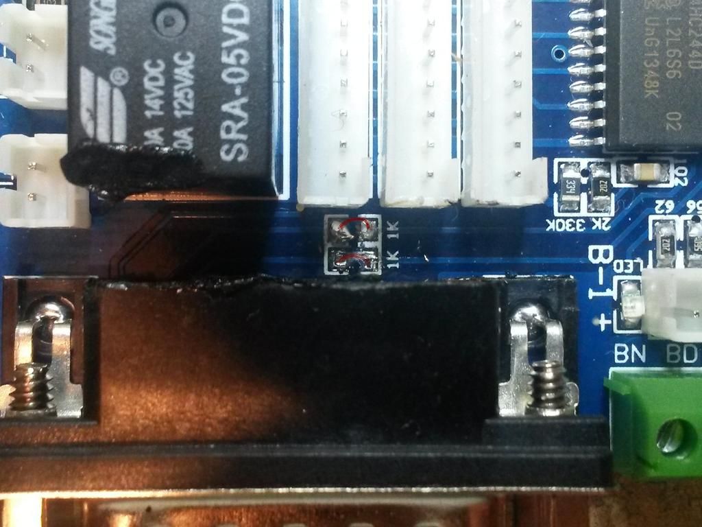
the simplest will be to short circuit the two 56 ohm resistors connecting the b axis step & dir signals
from the 15 pin connector to the 74HC244
then add the replacement 56 ohm resistors inside the manual controls cable
Attachment 291220
a possible alternative is to cut the tracks to the D-Type connector pins 1 & 2
and solder the new 56 ohm resistors across the breaks
then use some KYNAR wire to connect the display connector pins 12 and 13 to the 74HC244 input pins 11 & 13
you will need to find (or drill) two holes to pass the wire from one side of the board to the other
Attachment 291222
I'd expect the display to work without the mod !
John
-
09-02-2015, 07:42 AM #1111
Registered
- Join Date
- Aug 2015
- Posts
- 5
Re: Electronic home switches made easy!
Hi John, Thanks for the pictures. pleas be patient with me while I go through this with you as I'm new to this stuff Originally Posted by john-100

If I go with the second method do I have removed the two resistors in the picture below: Do i put a link, like in the picture below or leave them as is?
Also please look at this picture to see If I understand.
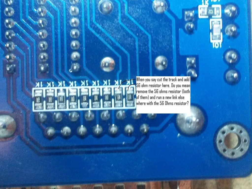
or do I remove them and add a 56 resistor between the two links. sorry for all the silly questions.
-
09-02-2015, 11:31 AM #1112
Registered
- Join Date
- Mar 2007
- Posts
- 2083
Re: Electronic home switches made easy!
Hi Mrrex
with the second and more complex fix , the two 56R resistors are removed
Attachment 291300
and the PCB tracks to the 15 way D-Type connector pins 1 & 2 are cut
Attachment 291302
after bridging the cuts with the 56R resistors you now have 11 resistors in a row instead of 9
Attachment 291306
you now have to connect the display connector pins 12 & 13 to the 74HC244 pins 11 & 13
the wire connected to the display connector needs to pass through the board to connect to
the PCB tracks connected to the IC pins
Attachment 291308
possible route for wire through PCB
Attachment 291310
as an alternative to KYNAR wire
try 34 AWG enamelled wire as used in the VERO wire wrap system
john
-
09-02-2015, 12:18 PM #1113
Registered
- Join Date
- Aug 2015
- Posts
- 5
Re: Electronic home switches made easy!
Thank you so much John. that's perfectly clear now.
Originally Posted by john-100
-
09-04-2015, 01:43 AM #1114
Member
- Join Date
- Feb 2005
- Posts
- 829
Re: Electronic home switches made easy!
I have been using Falcon69's limit switch kit for many months now and I really love it. Very repeatable. My CRP4896 repeats to within .002, or less on every home, many times it repeats to .000!
-
02-05-2016, 03:25 AM #1115
Registered
- Join Date
- Jan 2013
- Posts
- 52
Re: Electronic home switches made easy!
Thats something I was wondering, I'm interested in these switches as homing switches, but I'm also curious because I want to put them on my slaved y axis to correct for any racking that may be present. How does one adjust in the control software? Mach 3 has this capability? Originally Posted by RomanLini
-
02-05-2016, 01:01 PM #1116
Community Moderator
- Join Date
- Mar 2003
- Posts
- 35538
Re: Electronic home switches made easy!
Mach3 by itself does not have this capability. But I believe that certain motion controllers for Mach do, because the motion controllers handle the homing.
Gerry
UCCNC 2017 Screenset
http://www.thecncwoodworker.com/2017.html
Mach3 2010 Screenset
http://www.thecncwoodworker.com/2010.html
JointCAM - CNC Dovetails & Box Joints
http://www.g-forcecnc.com/jointcam.html
(Note: The opinions expressed in this post are my own and are not necessarily those of CNCzone and its management)
-
03-06-2016, 10:00 PM #1117
Registered
- Join Date
- Jan 2013
- Posts
- 52
Re: Electronic home switches made easy!
Has anyone used these in conjunction with mechanical limit switches? Have the hall effect on one side of the axis for homing, and the mechanical at the other end? If you were to do this, are you somehow able to wire these together to utilize one input?
Thanks!
-
03-06-2016, 11:16 PM #1118
Gold Member
- Join Date
- Mar 2004
- Posts
- 1806
Re: Electronic home switches made easy!
The hall effect is effectively a NO (Normally Open) switch. Therefore, you need to use a NO mechanical switch and wire them in parallel.
Art
AKA Country Bubba (Older Than Dirt)
-
03-07-2016, 04:51 AM #1119
Registered
- Join Date
- Nov 2010
- Posts
- 520
Re: Electronic home switches made easy!
Well I don't know if this is what you mean by "in conjunction with", but I do use both hall effect switches and mechanical limit switches on the same machine. I have the mechanical switches (5 of them) wired in series for the limit. It's not really important to me which axis trips the limit, just stop already. I have a hall switch on the X axis and one on the Y axis for homing. Each hall switch has it's own input on the G540 and all the limit switches are wired into one input on the G540. So I am only using 3 inputs on the G540. When I ref all home, both the X and Y axis will move at once until each trips the home switch (hall effect). Originally Posted by blitz355
Works great.
Hope this helps.
Rick
-
03-07-2016, 04:33 PM #1120
Registered
- Join Date
- Sep 2005
- Posts
- 106
Re: Electronic home switches made easy!
Rick,
How are your hall effect switches wired? I upgraded to the 540 a couple of years ago, but the halls I have are only 5v, and the 540 puts out 12v (that might be wrong I haven't looked at it in awhile, I just remember it was higher than the halls would work on)
Thanks
Ray

 Reply With Quote
Similar Threads
-
Omni tech CNC 1212 does this machine have Limit switches and Home switches.
By zlswain in forum Chinese MachinesReplies: 3Last Post: 11-05-2013, 02:54 AM -
Home made electronic for Spindle control
By dinko in forum CNC Machine Related ElectronicsReplies: 1Last Post: 05-31-2012, 02:52 PM -
Auto backlash sensing with electronic home switches!
By RomanLini in forum Open Source CNC Machine DesignsReplies: 8Last Post: 11-14-2011, 02:36 PM -
The relationship of limit switches to home switches.
By MikeAber in forum CNC Machine Related ElectronicsReplies: 4Last Post: 11-04-2004, 08:28 PM -
Home made CNC mill (and some products made by it)
By gcamlibel in forum DIY CNC Router Table MachinesReplies: 23Last Post: 04-05-2004, 11:54 PM
