

Looking good!
Thread: Slant bed CNC lathe from scratch
Results 201 to 220 of 405
-
01-15-2009, 10:28 PM #201
 Registered
- Join Date
- Aug 2005
- Posts
- 96
-
01-17-2009, 03:41 PM #202
Registered
- Join Date
- May 2006
- Posts
- 573
Hi guys
I need a little help here. Im confused. Today i fired up the transformer and did some mesuring. This is what i got when i mesured the AC between earthing here in the workshop and the PSU. When i turn of the power i get a reading of 3-4V~.
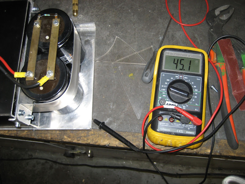
From CNC
I actually added a insulating piece of acrylic between the transformer and the alu plate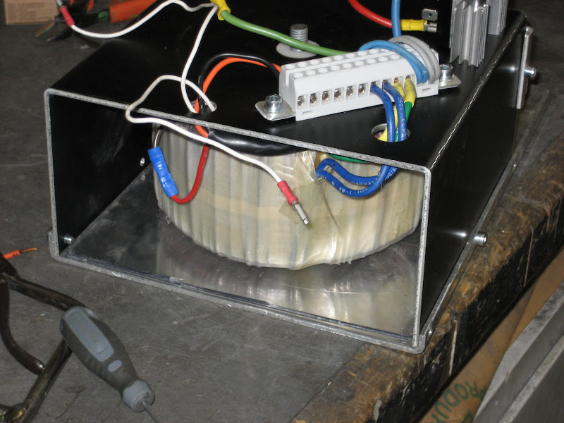
From CNC
I mesured and there is absolutly no contact between either the primary or the secondary circuit and the alu plate. I dont understand how the transformer can generate this amount of voltage without contact? Also the reading is suspicious close to the reading of the two secondary circuit?
-
01-17-2009, 04:19 PM #203
Registered
- Join Date
- May 2006
- Posts
- 573
Hmm, problem identified. After moving the center bolt the voltage dropped to 9V~. Apperently a circuit wasnt necessary to create a whole lot of voltage, glad i tested it :-s I hate! messing with high current.
I still get a increase in the voltage in 5-6V~. Is this acceptable? I plan to earth the whole machine with 6mm2 wire from each vital part
-
01-17-2009, 07:05 PM #204
Registered
- Join Date
- May 2006
- Posts
- 573
Damn, problem still not solved. Dont know why, but it now shows a 110V~ difference between earth and the alu plate. I can earth the problem away, but im not quite satisfied with it. Is this normal when working with large transformers?
-
01-17-2009, 07:38 PM #205
Registered
- Join Date
- Aug 2008
- Posts
- 573
It is quite normal to find any piece of unearthed chassis floating up to apparently high voltages (that's why they should be earthed); the result of capacitance coupling, leakage etc. Check with the AC current range on the multimeter, there should be only uA (micro-amps) of current flowing back to a proper earth. Originally Posted by Guldberg
 Bill
Bill
-
01-17-2009, 07:46 PM #206
Registered
- Join Date
- Apr 2007
- Posts
- 90
HI,
I am following your thread for a few days. Nice build Pal seems lot of planning and hardwork has been done. are you trying to mount a chuck or Collect. Any tech spec on the whole project. Just planning to make one little more bigger for my Jobs rather to machine them manually.
Vishnu
-
01-24-2009, 01:09 AM #207
Registered
- Join Date
- Sep 2006
- Posts
- 33
Hi,
Using a digital volt meter near the transformer will give you all sorts of weird readings!!!!
Do you have an analog volt meter?
Measure with that and I think all your "problems" will dissapear!
Just my experiences!!
Stick the two probes of a digital meter into oposite sides of an orange and tell me what voltage the orange generates?
Regards
John O R
-
01-24-2009, 02:36 PM #208
Registered
- Join Date
- Aug 2008
- Posts
- 573
Using a digital volt meter near the transformer will give you all sorts of weird readings!!!!
The reason typical 10Mohm input 'digital' meters apparently 'pick-up' odd readings is because they are better voltage meters than a typical 1kohm or 20k ohm/volt 'analogue' meter.
i.e. there really are odd 'voltages' floating around transformers (actually there is a conciderable magnetic field that will induce currents, hence 'voltages' in any conductor near the transformer)
In fact, both type of meter are actually measuring the current flowing through a known resistance i.e. they both require a small flow of current to 'see' anything. They both require a tiny amount of power from the source in order to report the voltage. A true 'voltmeter' would not require any current (hence power) at all.
[even though the 'digital' meter has a battery to run its electronics, it still requires a tiny amount of power from the source]
If you are not aware of this then 'digital' meters can cause confusion (BTDT) so, I agree with John sometimes an insensitve 'analogue' meter can be better
BTW if you probe and orange with a 'digital' meter you will get a reasonably accurate reading of the voltage generated by the chemical reactions between the acid in the orange and the metal of the probe. Do the same with with an insensitive 'analogue' meter and the reading will be less. Why? because althought the 'orange' does generate a small voltage the Power available is too small to drive the insensitive meter properly.Bill
-
01-24-2009, 02:46 PM #209
Registered
- Join Date
- May 2006
- Posts
- 573
Its all coming clear now:-) Im glad it wasnt a leak somewhere, though it would have been nice to know before i spend a couple of hours scratching my head and trying all sorts of things. Someday when im confidence enough with machining ill have to take some time to learn how this electronic stuff works.
Ive painted the base frame again and used a lot of hours removing all the electronics of the mouting plates, sanding them down, refitting the electronics and doing the final wirering. It takes a lot of time, but is hardly worth a picture
-
02-04-2009, 11:17 AM #210
Registered
- Join Date
- May 2006
- Posts
- 573
Finally some real progress. Its good to get to work with some metal after all that wiring.
The parts for the carriage as they arrived from the laserman as he named himself
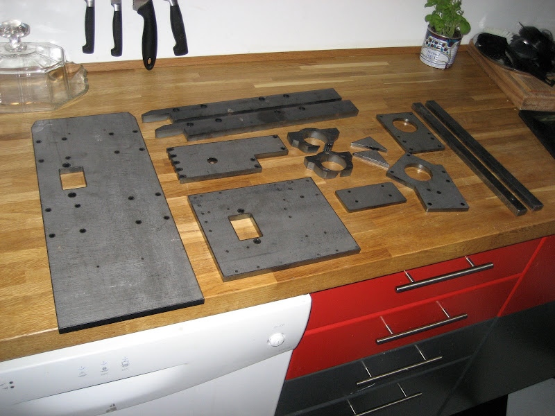
From CNC
Now off to the workshop...
Parts prepared and tacked together
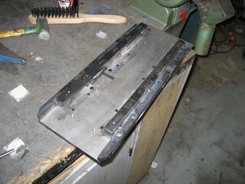
From CNC
I pulled out the big vise and milled it flat on both sides. Here are some in progress picture
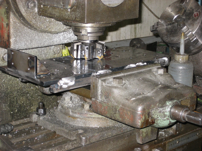
From CNC
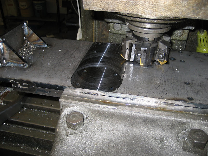
From CNC
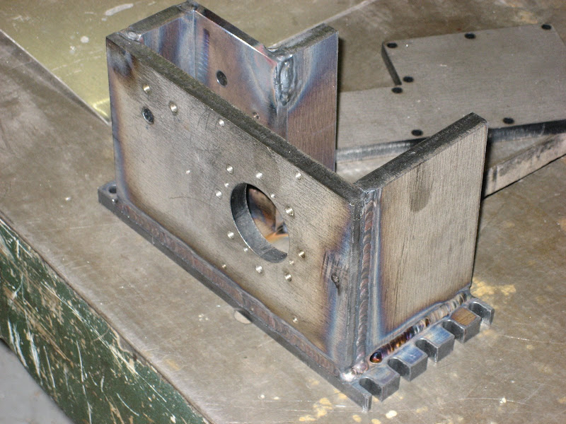
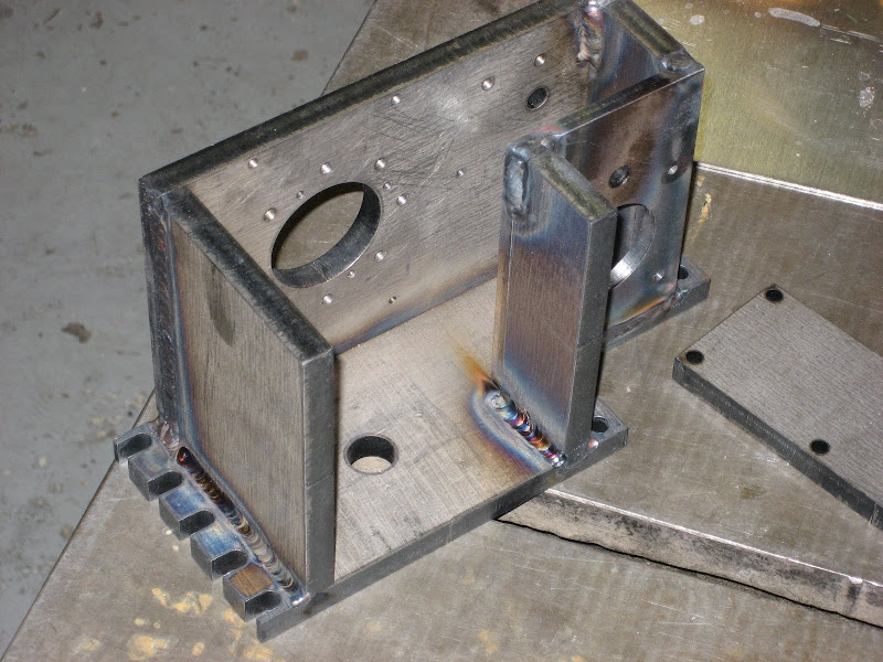
And the final result
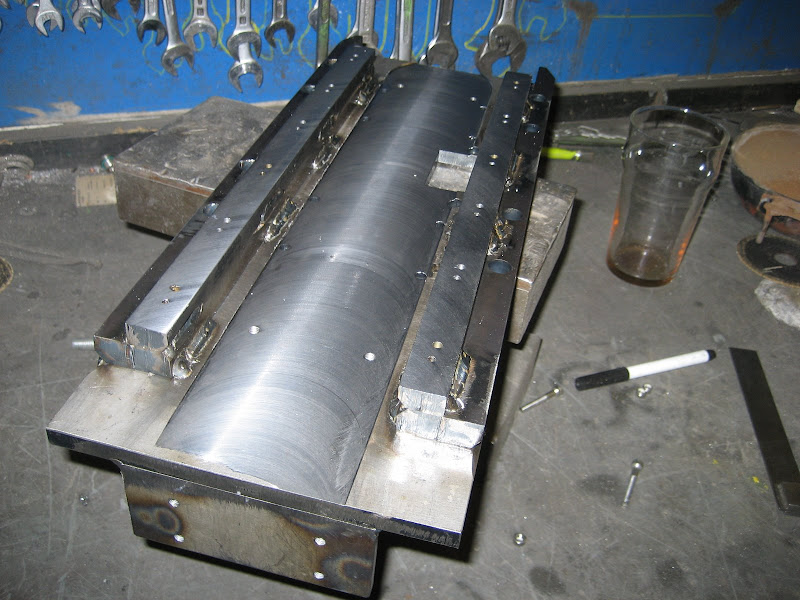
From CNC
From CNC
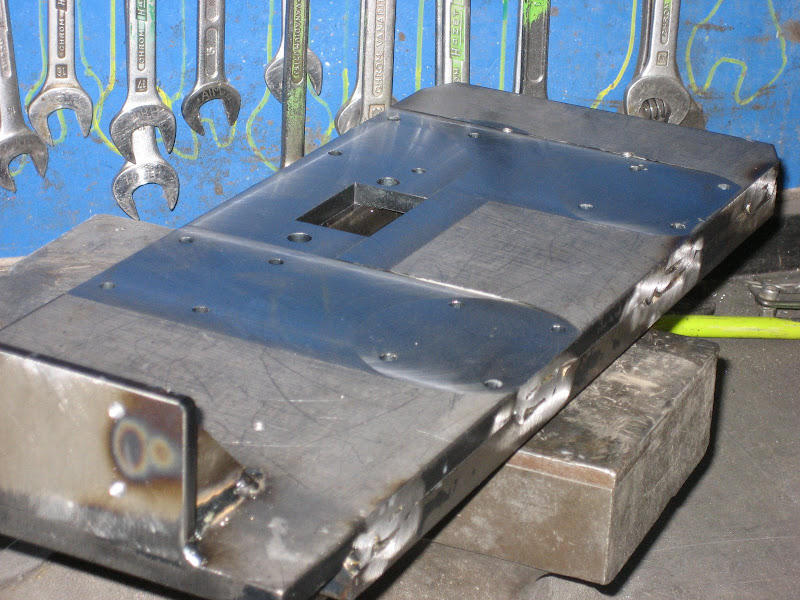
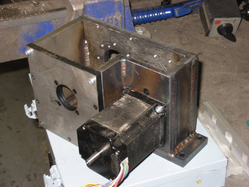
With the parts came also the bottom for the turret, so a friend of mine TIG'ed together for me, look at those beautiful welds, sure looks better than MIG/MAG welding
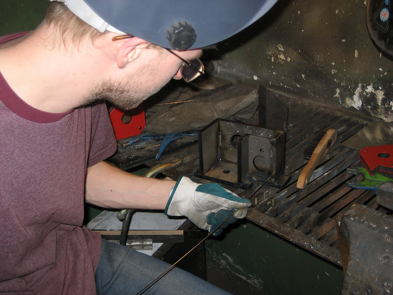
From CNC
From CNC
From CNC
Lastly a little video showing how to clear out any chips forgotten in the PSU...
From CNC
More pics can be seen if you follow the link to the picasa album
-
02-06-2009, 03:35 PM #211
Member
- Join Date
- Jun 2006
- Posts
- 474
Once again...... VERY NICE!!!!!
Chich
-
02-08-2009, 10:12 AM #212
Registered

- Join Date
- Apr 2006
- Posts
- 169
VERY NICE
:wee::wee::wee::banana::banana::banana:
-
02-08-2009, 12:05 PM #213
Registered
- Join Date
- May 2006
- Posts
- 573
Spend the last two days in the workshop, made quite a progress despite some hangovers:-)
Turned the bracket for the x axis motor
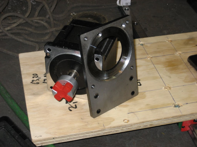
From CNC
Mounted the motor and rails. Also made a bracket for the limit and homing switches. Limits are proximity switches and homing is a precision switch with 0.01mm repeatability accuracy. The bracket also work as a hard stop to prevent the carriages from being damaged
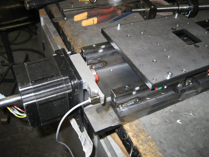
From CNC
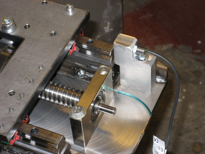
Ballscrew mounted and aligned
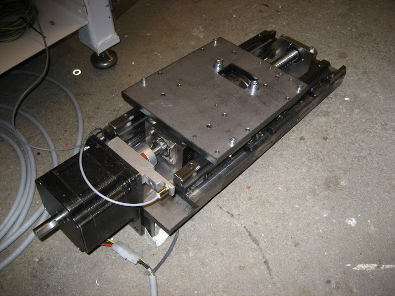
From CNC
From CNC
Not that exciting, but here is a video of the axis running back and forth at 5 m/min
Lastly I also milled the edges of the turret and drilled and taped the holes for the back plate
From CNC
-
02-09-2009, 08:32 PM #214
Registered
- Join Date
- May 2006
- Posts
- 573
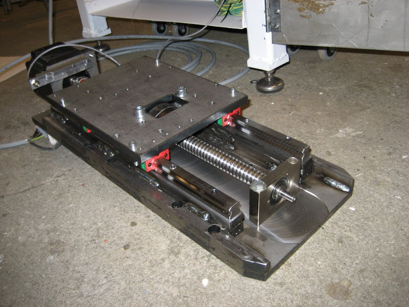
Both limits are now installed. I adjusted the speed to 2500mm/m which means that even at full speed the slider stops before it hits the dead stop when tripping the limits.
I have a question though, how do you connect proximity switches in series, so i dont have to use a pin per switch. Do i simply connect signal of one of them to ground on the other?
From CNC
-
02-09-2009, 11:06 PM #215
Registered
- Join Date
- Aug 2008
- Posts
- 573
What sort of proximity switch? (i.e. part number etc.) I'll look it up for you.
Bill
-
02-09-2009, 11:08 PM #216
Gold Member
- Join Date
- Apr 2005
- Posts
- 1778
I have been mulling over a similar question for sometime. I was thinking about using a quad 2 input AND gate. Feed the outputs of the switches to a pair of gate inputs. As long as both inputs were high, the output would be high but if either switch output (gate input) went low, the gate output would go low. Wire the gate output to your parallel port input pin. (This of course assumes that your switches trigger low). If they are normally low and trigger high then you could do the same but with an OR gate. Originally Posted by Guldberg
Alan
-
02-11-2009, 01:31 AM #217
Gold Member
- Join Date
- Aug 2006
- Posts
- 1602
Wow, this really is a fantastic build!
I would have thought that you would need some kind of logic in there to combine the signals - the proximitiy sensors that I've seen need power & ground to run their own internal logic, and provide a logic-level ouput to show whether they're triggered or not.
You can build simple gates with a couple of discrete components (diodes, resistors and transistors) if you don't have any suitable low-voltage supplies to run an IC.
One thing that does worry me though - you seem to have a delicate proximity sensor in harms way if the carriage overshoots. Can't you sense the edge of the table sideways, so that it'll just glide past the sensor if it overruns?
-
02-11-2009, 10:03 AM #218
Registered
- Join Date
- May 2006
- Posts
- 573
Thank for all for the nice words
As for the proximity sensor. No worry, its sitting out of harms way, just behind the dead stop
-
02-12-2009, 08:54 PM #219
Gold Member
- Join Date
- Sep 2006
- Posts
- 1738
Great work on the axis. Looks very solid.
-Jason
-
02-18-2009, 10:56 AM #220
Registered
- Join Date
- May 2006
- Posts
- 573
Disassembled the carriage and painted it white. Came out just fine. It merely for protection, none of this is going to be visible when its finished.
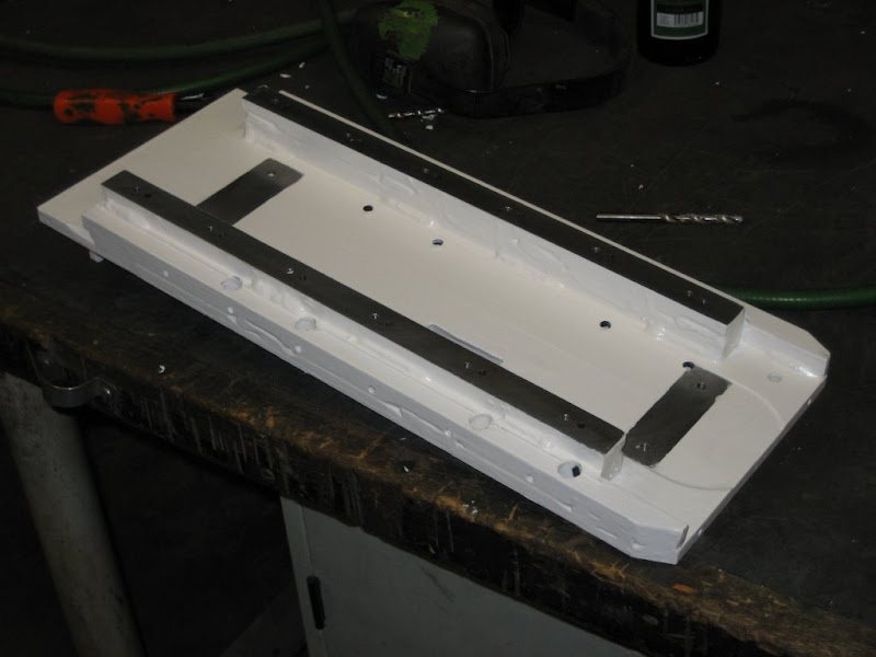
From CNC
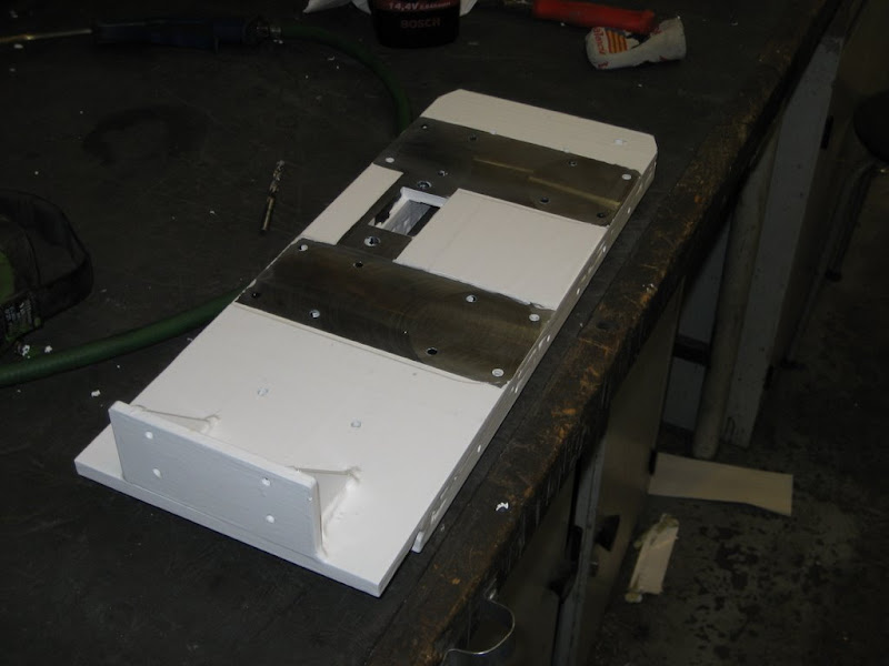
From CNC
I remounted the rails and aligned them. It was a lot easier than i excepted, got it down to a variation of +- 0.01mm along the length of the rail.
Did a test run with the acceleration set to 900 and max feedrate set to 6500. The computer wouldt go any higher at 35kHz kernel speed, but the axis moved just perfect. Im gonna set the speed to 2500 anyway, so it doesnt really matter

 Reply With Quote
Similar Threads
-
CNC lathe scratch build!
By aarongough in forum Vertical Mill, Lathe Project LogReplies: 37Last Post: 02-07-2013, 10:06 PM -
Looking for Specs for a scratch built lathe
By breathe in forum Vertical Mill, Lathe Project LogReplies: 18Last Post: 06-16-2011, 12:56 PM -
From scratch. Lathe, Mill, or maybe both.
By MrBean in forum Vertical Mill, Lathe Project LogReplies: 27Last Post: 10-28-2010, 01:25 PM -
CNC Lathe from Scratch
By mackeym in forum Vertical Mill, Lathe Project LogReplies: 85Last Post: 06-02-2010, 12:20 AM
